
Cooperating defibrillators and external chest compression devices

a technology of external chest compression and defibrillator, which is applied in the direction of artificial respiration, heart stimulation, therapy, etc., can solve the problems of synchronizing the functions of the two functions, and affecting the effect of cardiac and/or respiratory arres

Active Publication Date: 2008-05-15
PHYSIO CONTROL INC
View PDF9 Cites 14 Cited by
  • Summary
  • Abstract
  • Description
  • Claims
  • Application Information

AI Technical Summary

Benefits of technology

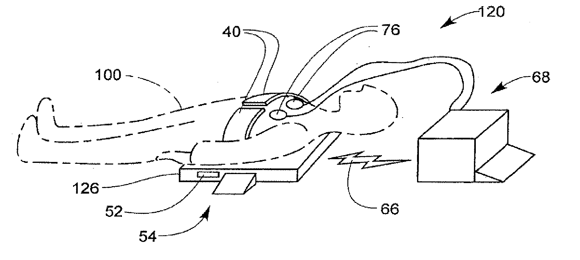
[0014] One method according to the present invention includes placing a person on a first device, establishing data communication between the first device and a second device that can be physically apart from the first device, causing a chest compression member of the first device to compress the chest of the person against the backboard, and causing a defibrillator of the second device to defibrillate the person responsive to the communication. Placing the person on the first device can refer to placing the person on a portion of the first device, for example on a backboard, or on a vest or belt which encircles the person. Some embodiments utilize a constrictive vest or belt and do not include a backboard or backframe. The communication may be used either to synchronize the delivery of the defibrillator shock with an optimal time in the compression cycle, or to avoid applying the defibrillator shock at a vulnerable period in the compression cycle. The communication about defibrillator activity may, in turn, be used to initiate, pause, or terminate chest compressions, or to change operating parameters of the ECC device, such as rate and / or depth of chest compression. In some methods, placing the person on a backboard of the first device results in the person contacting a defibrillator electrode of the first device.
[0020] Each independent therapies may be applied alone or in combination. But a patient in cardiac arrest may benefit most from a synchronized combination of therapies, based on sensor readings. This could occur when a patient has been placed on an ECC device and instructions generated to establish communication between a first data communication module operably coupled to the ECC device and a second data communication module coupled to a defibrillator. Sensors may determine that a patient is in cardiac arrest, and, for example, may further indicate that the patient has been in a non-perfusing state for a period longer than 5 minutes. The device would recognize that a period of chest compressions should be initiated, sufficient to perfuse the patient, for two minutes before applying a defibrillation shock. The effectiveness of chest compression could be monitored, and the duration of stimulated perfusion measured. After two minutes, a defibrillation shock could be automatically applied. It may be desirable to initiate the shock during a chest compression, or between them, with such synchronization being performed to enhance shock effectiveness. Sensors detecting the reappearance of a perfusing ECG rhythm may initiate a 30-second period of pacing to further stimulate cardiac function. Alternatively, failure to restore a perfusing rhythm may cause a further period of CPR, followed by another defibrillation shock, to be administered. In all cases available therapies can be synchronized and combined in ways responsive to the patient's condition, and in ways that complement each other's effectiveness.

Problems solved by technology

For example, both in and out of the hospital, there is a significant incidence of cardiac and / or respiratory arrest among at-risk patients.
Many of the prior art devices, however, merely collect such features into a single package, without synchronizing their functions and making them work together.

Method used


Image

  • Cooperating defibrillators and external chest compression devices
  • Cooperating defibrillators and external chest compression devices
  • Cooperating defibrillators and external chest compression devices

Examples


Embodiment Construction

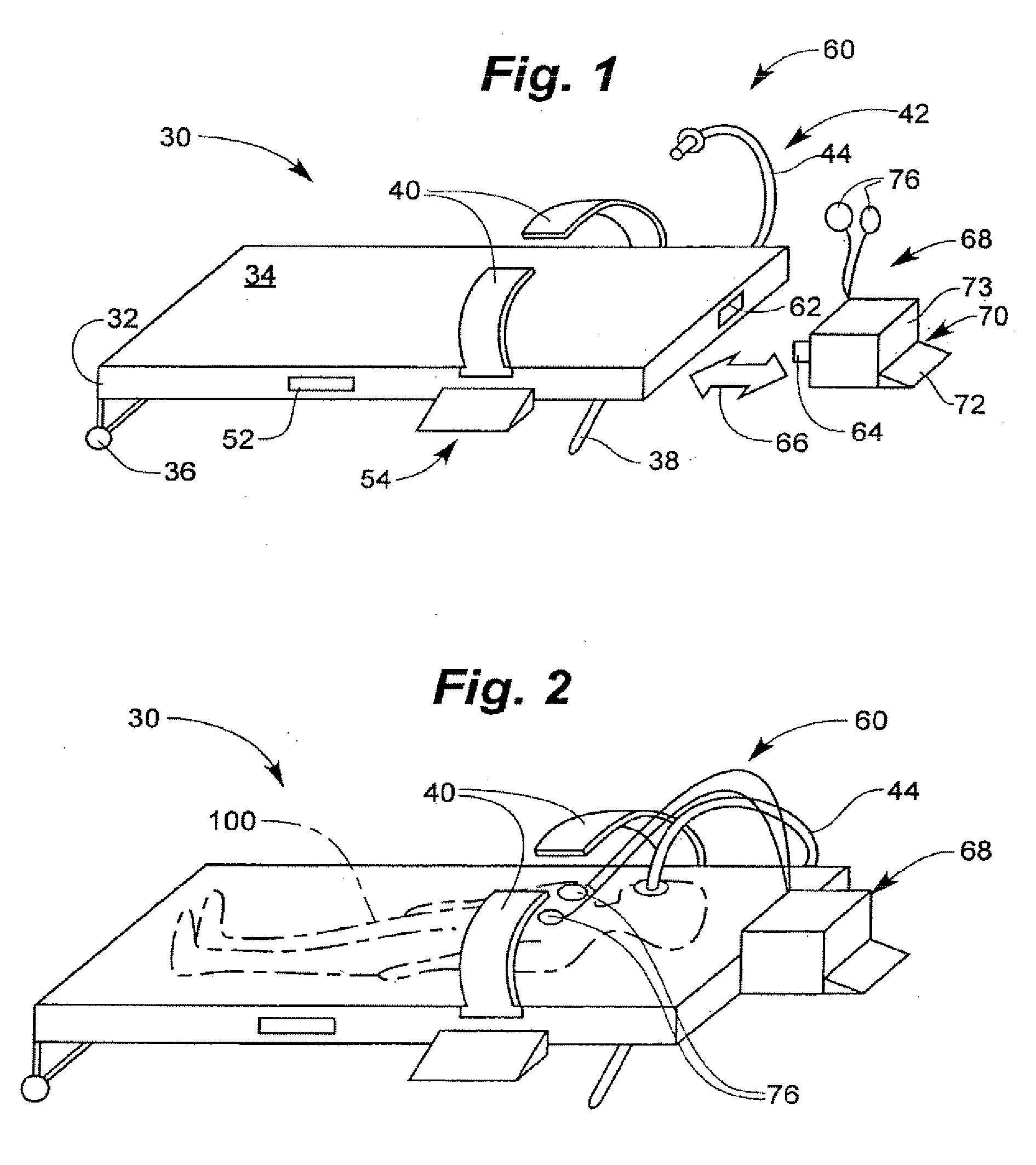
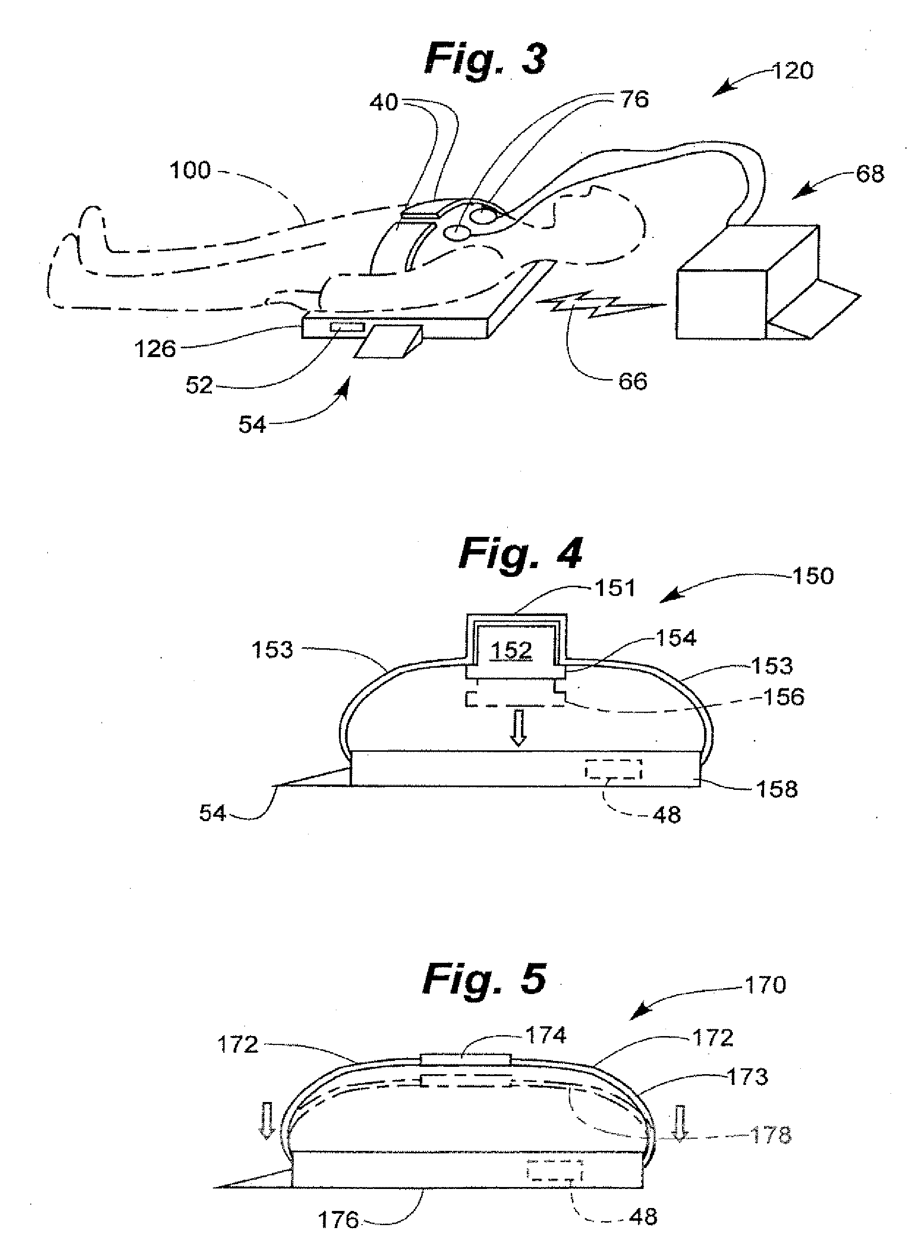
[0047] According to the invention, an external chest compression (ECC) device is provided, and also an external defibrillator. In addition, each has an interface for communicating with the other, and optionally also for cooperating for maximum effect. The interfaces are made compatible with each other, as further described below.

[0048] An important aspect of the invention is that the external defibrillator is capable of functioning autonomously, independently of the external chest compression device when they are not communicating or cooperating. It is also highly preferable that the external chest compression device be capable of functioning autonomously, independently of the external defibrillator when they are not communicating or cooperating.

[0049]FIG. 1 illustrates a system 60 for performing coordinated ECC and defibrillation including an external chest compression (ECC) device 30 and an external defibrillation device 68. ECC device 30 includes a backboard or back frame 32, c...


PUM


Abstract

Devices, methods, and software implementing those methods for providing communicating external chest compression (ECC) devices and defibrillation (DF) devices, where the ECC and DF devices can be physically separate from each other. Both ECC and DF devices are able to operate autonomously, yet able to communicate with and cooperate with another device when present. Some ECC and DF devices are adapted to be physically and / or electrically coupled to each other. One ECC device includes a backboard, a chest compression member, a communication module, controller, and at least one sensor, electrode lead or electrode. One DF device includes a defibrillator module, a controller, and a communication module that can communicate with the ECC communication module. The communicating ECC and DF devices may deliver ECC, pacing, defibrillation, ventilation, and cooling therapies, and may deliver instructions to human assistants, in a coordinated and cooperative fashion.

Description

RELATED APPLICATIONS [0001] This application is a continuation of U.S. patent application Ser. No. 10 / 652,148, fired on Aug. 29, 2003 which is hereby incorporated by reference in its entirety, and which claimed priority to U.S. Provisional Patent Application No. 60 / 447,587, filed Feb. 14, 2003, titled COOPERATING DEFIBRILLATORS AND CPR DEVICES, herein incorporated by reference in its entirety. The present application is related to U.S. patent application Ser. No. 10 / 652,392, titled INTEGRATED EXTERNAL CHEST COMPRESSION AND DEFIBRILLATION DEVICES AND METHODS OF OPERATION, and to U.S. patent application Ser. No. 10 / 652,965, titled DEFIBRILLATORS LEARNING OF OTHER CONCURRENT THERAPY, both filed on Aug. 29, 2003.BACKGROUND OF THE INVENTION [0002] 1. Field of the Invention [0003] The present invention is related to the field of resuscitation devices. [0004] 2. Description of the Related Art [0005] All over the world, people experience resuscitation events. For example, both in and out of...

Claims


Application Information

Patent Timeline
Patent Type & Authority Applications(United States)
IPC IPC(8): A61N1/39A61H31/00G16Z99/00
CPCA61H31/005A61H31/006A61H31/008A61H2201/0214A61H2201/5007A61H2201/501A61N1/39A61H2201/5048A61H2201/5058A61H2201/5097A61H2230/04A61M16/00A61M2202/0208A61H2201/5012G16H40/63A61N1/39044G16Z99/00
Inventor HAMPTON, DAVID R.STICKNEY, RONALD E.NOVA, RICHARD C.RADONS, STEPHEN W.EDWARDS, D. CRAIGJAYNE, CYNTHIASULLIVAN, JOSEPH L.SJOQUIST, STEVEN E.
Owner PHYSIO CONTROL INC
Learn More