Stable Initiator Compositions and Igniters
a technology of initiator composition and igniter, which is applied in the direction of make-and-break ignition, lighting and heating apparatus, instruments, etc., can solve the problems of large amount of gas generated by direct heating of solid fuel, large amount of power required to raise the temperature, and large amount of mass represented by solid fuel, etc., to achieve high sparking plume and sufficient energy
- Summary
- Abstract
- Description
- Claims
- Application Information
AI Technical Summary
Problems solved by technology
Method used
Image
Examples
example 1
Initiator Composition Embodiment
[0143] The following procedure was used to prepare a slurry of an initiator compositios comprising 23.7% Zr: 23.7% MoO3: 2.4% Laponite® RDS: 50.2% water.
[0144] To prepare wet Zirconium (Zr), the as-obtained suspension of Zr in DI water (Chemetall, Germany) was agitated on a roto-mixer for 30 minutes. Ten to 40 mL of the wet Zr was dispensed into a 50 mL centrifuge tube and centrifuged (Sorvall 6200RT) for 30 minutes at 3,200 rpm. The DI water was removed to leave a wet Zr pellet.
[0145] To prepare a 15% Laponite® RDS solution, 85 grams of DI water was added to a beaker. While stirring, 15 grams of Laponite® RDS (Southern Clay Products, Gonzalez, Tex.) was added, and the suspension stirred for 30 minutes.
[0146] The reactant slurry was prepared by first removing the wet Zr pellet as previously prepared from the centrifuge tube and placing it in a beaker. Upon weighing the wet Zr pellet, the weight of dry Zr was determined from the following equation:...
example 2
Initiator Composition Embodiment
[0148] An initiator composition was prepared by adding 8.6 mL of a homogenous 4.25% Viton A500 (Dupont) / amyl acetate solution to a mixture of 0.680 g of Al (40-70 nm, Argonide), 1.320 g of MoO3 (nanosized, Climax Molybdenum), and 0.200 g of boron (nanosized, Aldrich) and mixing well with an homogenizer blade. The mixture was homogenized at speed 1 for 30 seconds, then at speed 2 for 4 min.
example 3
Preparation of Igniter
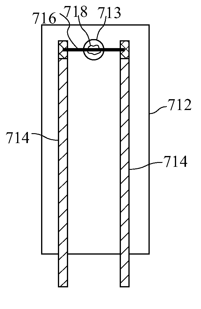
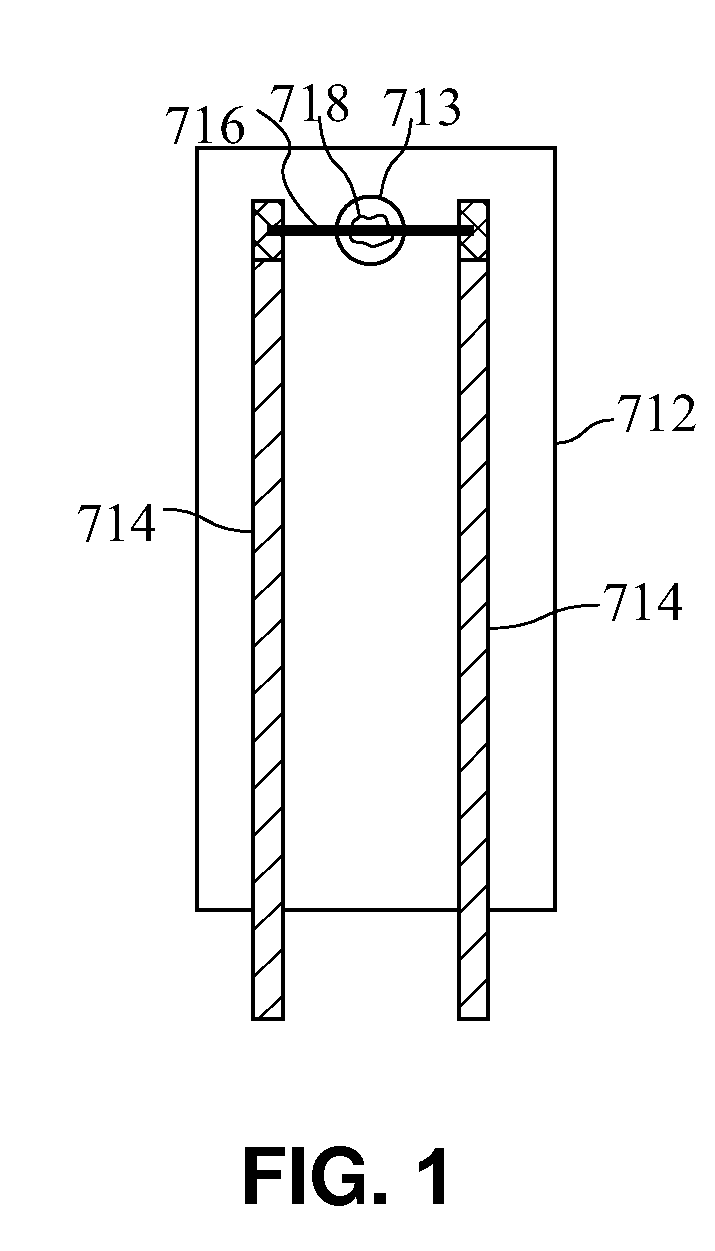
[0149] The ignition assembly comprised a cleaned 0.005 inch thick FR-4 printed circuit board (1.820 inches×0.25 inches) having a 0.03 inch diameter opening at one end and two copper tracings each 0.35 inches×1.764 inches, one on each side of the hole, printed along the length of the circuit board and a 0.0008 inch diameter Nichrome wire positioned across the opening and soldered to the gold plated copper tracings on the printed circuit board.
[0150] An initiator composition was prepared by adding 8.6 mL of a homogenous 4.25% Viton A500 / amyl acetate solution to a mixture of 0.680 g of Al (40-70 nm, Argonide), 1.320 g of MoO3 (nanosized, Climax Molybdenum), and 0.200 g of boron (nanosized, Aldrich) and mixing well with an homogenizer blade. A 1.1 μL drop of the initiator composition was placed on the Nichrome wire over the hole using a Cavro Syringe Pump. The initiator composition was allowed to air dry for 10 min. The igniter was turned over and an additional 0...
PUM
 Abstract
Description
Claims
Application Information
 - R&D
- Intellectual Property
- Life Sciences
- Materials
- Tech Scout
- Unparalleled Data Quality
- Higher Quality Content
- 60% Fewer Hallucinations
Browse by: Latest US Patents, China's latest patents, Technical Efficacy Thesaurus, Application Domain, Technology Topic, Popular Technical Reports.
© 2025 PatSnap. All rights reserved.Legal|Privacy policy|Modern Slavery Act Transparency Statement|Sitemap|About US| Contact US: help@patsnap.com


