
Operation apparatus

Inactive Publication Date: 2008-05-08
DENSO CORP
View PDF7 Cites 7 Cited by
  • Summary
  • Abstract
  • Description
  • Claims
  • Application Information

AI Technical Summary

Benefits of technology

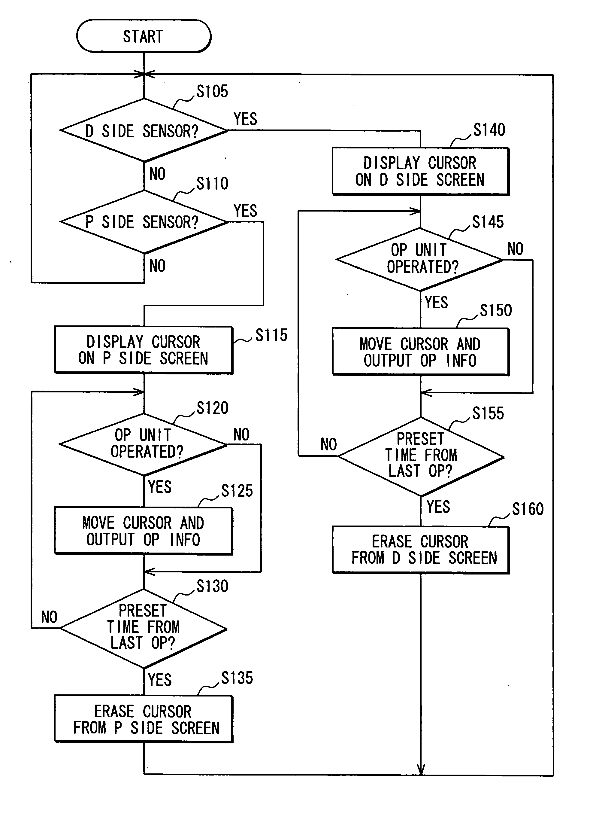
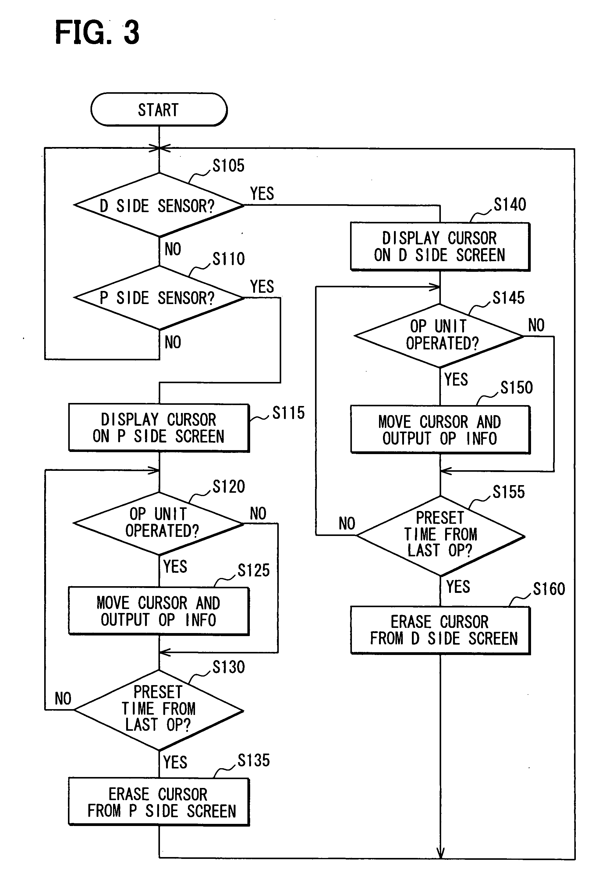
[0008] In view of the above and other problems, the present disclosure provides an operation apparatus that is used in combination with a dual view display apparatus for displaying two different images for respective users, and provides a “user distinguishability” for distinguishing respective users without compromising usability.
[0012] The operation unit is touched at different positions when the unit is operated manually by the left hand and by the right hand, due to an asymmetrical shape of the hand. More practically, there are positions only touched by the left hand in the course of the manual operation of the operation unit by the left hand, and there also are the positions only touched by the right hand in the course of the manual operation of the operation unit by the right hand. The inventor of the present invention arranged the first sensor at the position that is touched only by the left hand for an operation of the operation unit, and arranged the second sensor at the position that is touched only by the right hand for an operation of the operation unit based on the finding of those positions. As a result, the operation of the operation unit can be determined as either of the operation by the right hand or the left hand, and usability such as an arrangement of operation icons on the display unit is not restricted. That is, the usability of the operation apparatus is not compromised due to the improvement regarding the determination function for determining the operator of the operation unit.

Problems solved by technology

However, the restriction on the space or position for installing the operation unit in the vehicle makes it difficult to have separate operation units for both of the driver's seat and the passenger's seat.
However, the technique described above has a restriction on the number of the operation icons on the screen as well as a restriction on an arrangement of the operation icons on the screen.
Therefore, the usability of the display apparatus using the above technique is deteriorated in comparison to the normal display apparatus having only one image on the screen.

Method used


Image

  • Operation apparatus
  • Operation apparatus
  • Operation apparatus

Examples


Embodiment Construction

[0019] An embodiment of the present invention is described with reference to the drawings. The embodiment of the present invention is not limited to the following descriptions, but is in various forms as long as they pertain to the scope of the invention.

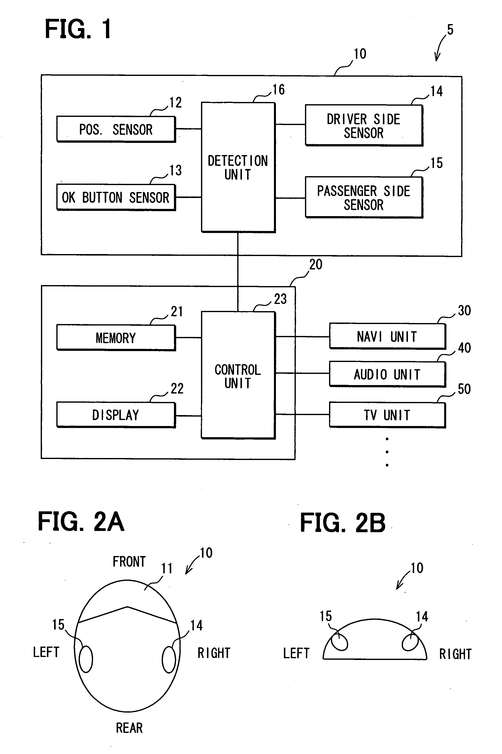
[0020]FIG. 1 is a block diagram showing an outline configuration of an operation system 5 for use in a vehicle in the present embodiment. The operation system 5 includes an operation unit 10 and a display unit 20 and a the navigation unit 30 and an the audio unit 40 and a television (TV) unit 50.

[0021] The operation unit 10 includes a position sensor 12, an OK button sensor 13, a driver side sensor 14, a passenger side sensor 15 and a detection unit 16 with each of those sensors being connected to the detection unit 16.

[0022] The operation unit 10 is disposed at a position in the vehicle between a right front seat and a left front seat for both of an operator (i.e., may also be referred to as a “driver” hereinafter) in the right ...


PUM


Abstract

A manually operated operation apparatus that is combined with a display apparatus for showing a different image for respectively different occupants includes a driver sensor at a position being touched by a driver who operates an operation unit, a passenger sensor at another position being touched by a passenger who operates the operation unit. Based on a detection result of these sensors, the operator of the operation unit is determined. In this manner, the operation apparatus distinguishes the operator of the operation unit for removing a limitation on an operation icon being displayed on the display apparatus without imposing a special operation on a user, thereby enabling an improvement of the usability of the operation apparatus.

Description

CROSS REFERENCE TO RELATED APPLICATION [0001] This application is based on and claims the benefit of priority of Japanese Patent Application No. 2006-303106 filed on Nov. 8, 2006, the disclosure of which is incorporated herein by reference. FIELD OF THE DISCLOSURE [0002] The present disclosure generally relates to an operation apparatus for use in a vehicle in combination with a dual view display apparatus. BACKGROUND INFORMATION [0003] In recent years, a display apparatus called “Dual View Display” is known for use in a vehicle. The Dual View type display apparatus displays two different images on one screen to be viewed simultaneously from two different viewing directions. [0004] When the Dual View type display apparatus is used in a navigation apparatus, it is convenient for the occupants in both of the driver's seat and the passenger's seat because respective occupants see a different image that serves their respective purposes appropriately. However, when the occupants in the d...

Claims


Application Information

Patent Timeline
IPC IPC(8): G09G5/00
CPCB60K37/06G06F3/04886B60K2350/903B60K2350/901B60K35/10B60K35/656B60K35/654
Inventor SHIBATA, SHINJI
Owner DENSO CORP
Learn More