
Hose clamp

Active Publication Date: 2008-05-01
NORMA GERMANY GMBH
View PDF5 Cites 26 Cited by
  • Summary
  • Abstract
  • Description
  • Claims
  • Application Information

AI Technical Summary

Benefits of technology

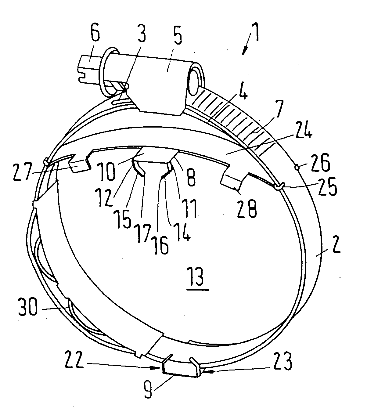
[0008] Therefore, it is the primary object of the present invention to simplify the preassembly of the hose clamp on the hose. In accordance with the present invention, in a hose clamp of the above-described type the above object is met by providing the claw with a portion which protrudes inwardly from the base in a pressing direction, wherein the claw has an end which includes an obtuse angle with the inwardly protruding portion.
[0011] In accordance with another preferred feature, the inwardly directed portion extends at a right angle to the base. This makes it possible to transmit the force which is exerted onto the base to the claw in the best possible manner. The portion attached to the base maintains in the area of the base this alignment at a right angle relative to the base. The claw is only deformed further away toward the end thereof. The term “at a right angle” is not to be understood in this case in the mathematically exact sense. However, the portion connected to the base should extend approximately parallel to the pressing direction. The angle preferably has a magnitude in the range of 110° to 160°. Particularly preferred are angles in the range of 120° to 150°. Pressing the claw into the wall of a hose works particularly well if the angle is about 135°. In that case, the end of the claw is displaced at least to such an extent in circumferential direction within the wall of the hose as it penetrates into the wall. Preferably, two claws emanate from the base, wherein the ends of the claws are directed toward each other. This results in a force equilibrium in the circumferential direction, i.e., it is no longer necessary to secure the base against a lateral displacement in the circumferential direction. When the two claws have been finally bent, the consecution has a shape which is similar to a whole paper clip.
[0013] Preferably, the base has a smooth outer side. This makes it easier to apply a tool. In addition, the smooth surface ensures that there are no elements which protrude radially outwardly and which would later be in the way of a person assembling the hose clamp. In the assembled state there are also no perturbing elements in the area of the positioner.
[0014] The base preferably protrudes at least with a section axially beyond the clamp band. Consequently, the claws can be pressed into the hose wall outside of a region in which the clamping force of the clamping band acts. This prevents the end of the clamp from being pressed completely through the hose wall as a result of the clamping force.
[0015] In accordance with another preferred feature, the base protrudes axially beyond the claw at least over a portion of the base. This makes it easier to position the hose clamp in such a way that the claw is arranged with a predetermined distance from the end face of the hose. It is only necessary to have the base flush with the end face of the hose. The positioner is preferably arranged at a spring bridge whose ends are connected to the clamp band. The spring bridge provides the advantage that the clamping band may have in the area of the positioner a certain distance from the positioner when the clamp band is not yet tensioned. When disassembling the hose, i.e., when releasing the clamp, the spring bridge has the advantage that it spreads apart the clamping band when the clamping device is released.
[0017] It is preferred in this connection that this spring bridge is arranged in the area of the clamping device. The spring bridge serves another purpose. It prevents an end of the clamping band and / or the clamping device from contacting the circumference of the hose with friction, when the hose clamp is tensioned. The movement which takes place during tensioning of the hose clamp between parts of the hose clamp takes place practically exclusively on the outer side of the spring bridge.

Problems solved by technology

However, after a very short penetration depth, the end is deflected toward the side.

Method used


Image

  • Hose clamp
  • Hose clamp

Examples


Embodiment Construction

[0024] As illustrated in the drawing, the hose clamp 1 has a clamp band 2 which is bent into a circular shape, so that an outer end 3 is located above an inner end 4. The two ends are connected by means of a clamping device 5. The clamping device 5 includes a clamping screw 6 which meshes with a threaded embossment 7. When the clamping screw is tightened, the two ends 3, 4 of the clamping band 2 are moved relative toward each other in the circumferential direction of the hose clamp 1, so that the inner diameter of the hose clamp 1 is reduced.

[0025] The purpose of this type of hose clamp 1 is to clamp a hose, not shown, onto a connection piece. The hose clamp 1 is placed on the hose. The hose is then pushed onto the connection piece and the hose clamp 1 is tensioned. It is advantageous in this connection if the clamping device 5 is placed on the hose in a different position and is held in this position, so that a person can apply a tool to the clamping screw 6.

[0026] For ensuring t...


PUM


Abstract

A hose clamp includes a clamping band, a clamping device and a positioning arrangement, wherein the positioning arrangement has at least one positioner with a base and a claw for being pressed into a hose wall. The claw has a portion protruding inwardly from the base in a pressing direction, wherein the claw has an end which forms with the inwardly protruding section an obtuse angle (α).

Description

BACKGROUND OF THE INVENTION [0001] 1. Field of the Invention [0002] The present invention relates to a hose clamp with a clamping band, a clamping device and a positioning arrangement which includes at least one positioner or positioning means with a base and a claw which can be pressed into a hose wall. [0003] 2. Description of the Related Art [0004] A hose clamp has the purpose of tightly clamping a hose onto a connection piece. For this purpose, the hose clamp is placed in the area of the connection piece around the hose and the clamping devices is actuated in order to hold the clamping band together around the circumference of the hose. As a result, the hose is held in a clamping manner on the connection piece. [0005] In order to be able to actuate the clamping device the person using the tool must place the tool against the clamping device. For this reason, many users of hose clamps require that the hose clamp is preassembled on the hose, so that it has at least in the circumfe...

Claims


Application Information

Patent Timeline
IPC IPC(8): F16L33/02
CPCF16L33/08Y10T24/1427Y10T24/1443Y10T24/1441Y10T24/1412Y10T24/1451Y10T24/1447
Inventor KRAUSS, MATHIAS
Owner NORMA GERMANY GMBH
Learn More