
Device and method for guiding a user to a communication position

a communication position and device technology, applied in the direction of near field communication devices, instruments, burglar alarm mechanical actuation, etc., can solve the problems of long antennas to achieve proper resonance, inconvenient use for users, and none of these conventional techniques are very useful, so as to reduce the offset of alignmen

Inactive Publication Date: 2008-04-24
SONY CORP
View PDF7 Cites 148 Cited by
  • Summary
  • Abstract
  • Description
  • Claims
  • Application Information

AI Technical Summary

Benefits of technology

[0090]An advantage of the image recognition aspect of the present invention is that the mobile phone's recognition of a particular target mark 28 can be utilized to control how or what functions / operating parameters are presented to the user. For example, particular target marks 28 are associated with particular vendors, service providers, etc. Upon recognizing a particular target mark 28, for example as a result of the guidance operations described above, the mobile phone 20 may control how the mobile phone operates in conjunction with the user.

Problems solved by technology

Due to their low RF operating frequencies, NFC devices, as well as other inductive-coupling based devices, require a long antenna to achieve proper resonance.
Conversely, when the antenna is embedded within a mobile phone or other portable device, it may not be so intuitive how the device should be positioned relative to the reader / writer as the typical user does not know where the NFC antenna is located in the device.
Such binary indications are generally satisfactory, but are not useful to a user if the user is having trouble finding the target mark due to unfamiliarity with the location of the antenna in the portable device.
Furthermore, none of these conventional techniques are very useful when the target device is a passive tag that does not transmit any RF signal.
Moreover, even in the case of a powered reader / writer the cues described above provide only an indication of how close the devices are but do not indicate how the portable device should be repositioned in order to improve the quality of the short-range link.

Method used


Image

  • Device and method for guiding a user to a communication position
  • Device and method for guiding a user to a communication position
  • Device and method for guiding a user to a communication position

Examples


Embodiment Construction

[0046]The present invention will now be described with reference to the drawings, in which like reference labels refer to like elements throughout.

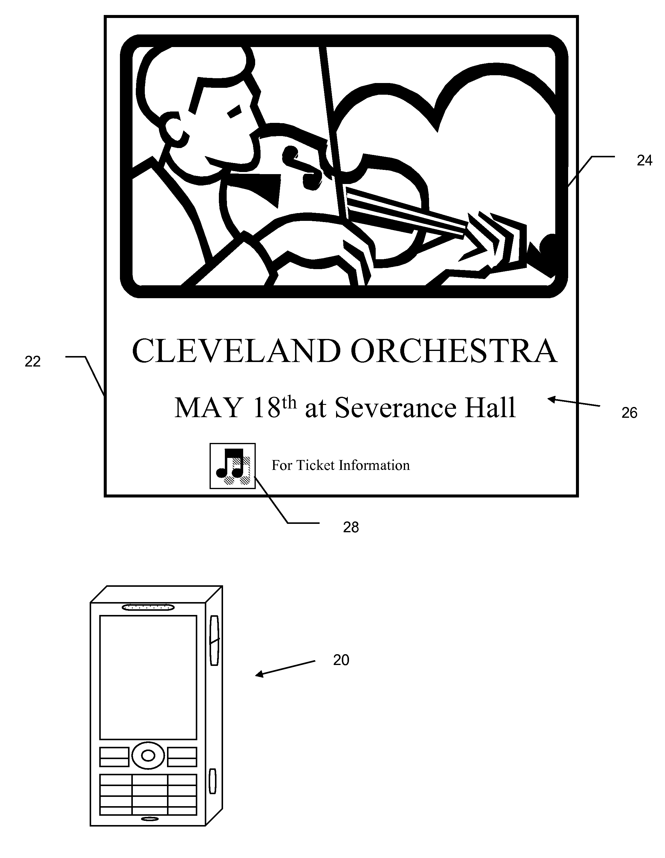
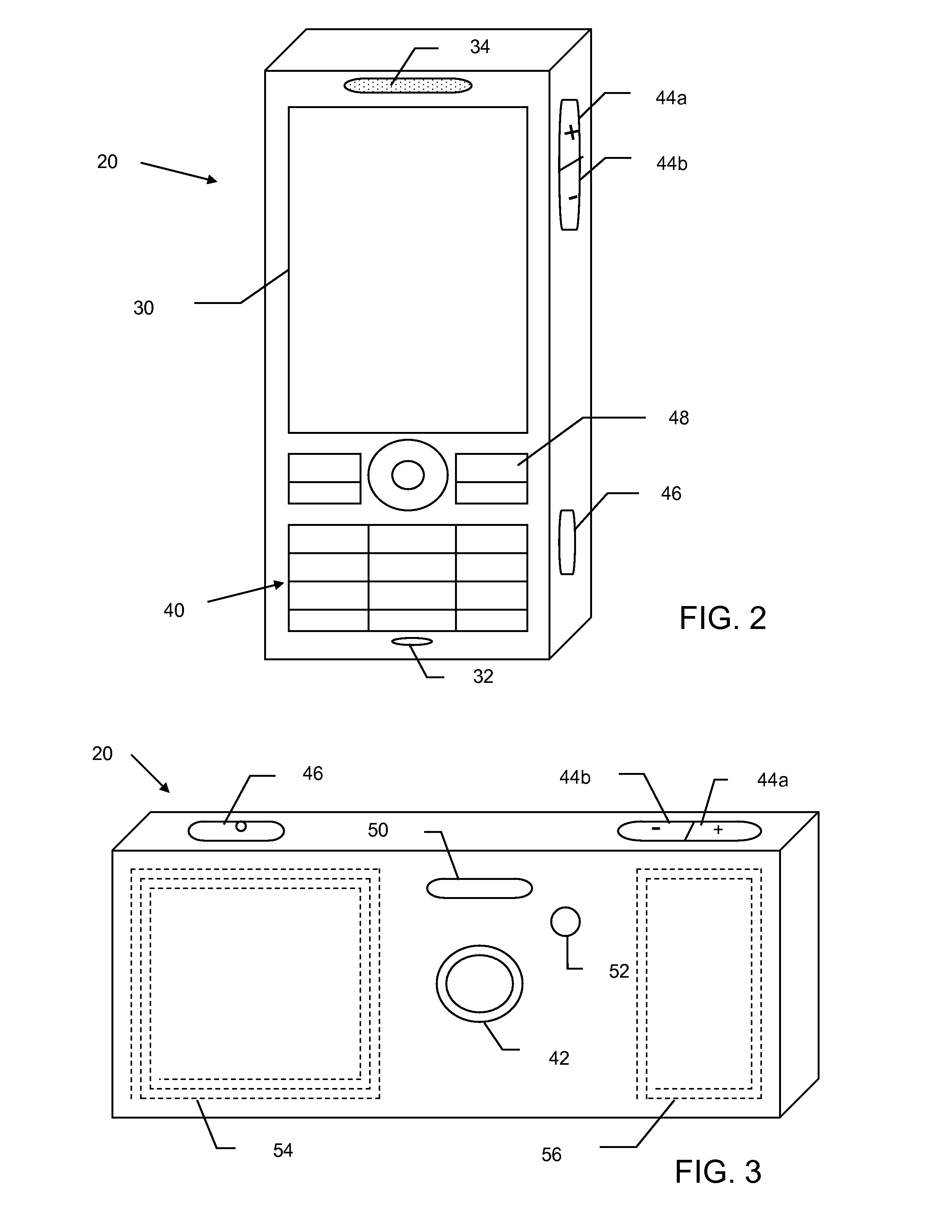
[0047]Referring initially to FIG. 1, a portable electronic device 20 is shown in accordance with an exemplary embodiment of the present invention. The portable electronic device 20, as will be explained more fully below, has NFC or other inductive-coupling based, short-range connectivity capabilities. Thus, the portable electronic device 20 is able to communicate with another NFC or similar type device.

[0048]For example, FIG. 1 illustrates an environment where a user of the portable electronic device 20 wishes to obtain information regarding an upcoming concert. A display 22 includes graphics 24 and / or text 26 telling of the concert. In addition, the display 22 includes one of the aforementioned NFC “target marks”28. The target mark 28 indicates to the user the ability to communicate data via NFC or similar inductive-coupling based techno...


PUM


Abstract

A portable electronic device that includes an antenna and at least one of a transmitter or a receiver connected to the antenna for transferring information between the portable electronic device and a corresponding device via the antenna. The corresponding device includes a visual indicator indicative of a location of an antenna of the corresponding device. The portable electronic device further includes an imaging device for obtaining an image of the visual indicator, an image analyzer for determining a location of the portable electronic device antenna relative to that of the corresponding device based on the image, a direction analyzer for determining a movement direction of the portable electronic device that would reduce an alignment offset between the antennas, and a directional indicator for indicating the movement direction to a user of the portable electronic device.

Description

TECHNICAL FIELD OF THE INVENTION[0001]The present invention relates generally to portable electronic devices and systems, and more particularly to a device and method for guiding a user to a communication position.DESCRIPTION OF THE RELATED ART[0002]Near Field Communication (NFC) is a short-range wireless connectivity technology designed for intuitive, simple and safe communication between electronic devices. NFC communication is enabled by bringing two NFC compatible devices within a few centimeters of one another or for the two devices to literally “touch” one another. Applications of NFC technology include contactless transactions such as payment and transit ticketing, simple and fast data transfers including calendar synchronization or electronic business cards and access to online digital content.[0003]NFC makes life easier for users—it's easier to get information, easier to pay for goods and services, easier to use public transport, and easier to share data between devices. As...

Claims


Application Information

Patent Timeline
Patent Type & Authority Applications(United States)
IPC IPC(8): G06K15/00G08B13/14H04M1/72412
CPCG06K9/228G06K9/3216H04N1/00307H04M1/7253H04M2250/52H04B5/0056H04M2250/04H04M1/72412G06V10/225G06V10/235G06V30/142G06V10/245H04B5/77
Inventor JOHNSON, PHILLIP MARCBLOEBAUM, L. SCOTT
Owner SONY CORP
Learn More