Surveillance camera and surveillance camera system with laser positioning function

a surveillance camera and laser positioning technology, applied in the field of surveillance systems, can solve the problems of inability to figure out the monitoring area, time-consuming and inconvenient whole process, and it is not easy for the installation staff to learn whether the focused monitoring area is exactly the required monitoring area, etc., to achieve the optimal installation angle and accurate and convenient installation

Inactive Publication Date: 2008-04-03
APPRO TECH
View PDF2 Cites 32 Cited by
  • Summary
  • Abstract
  • Description
  • Claims
  • Application Information

AI Technical Summary

Benefits of technology

[0007]Accordingly, the present invention is directed to provide a surveillance camera. The camera has a light beam positioning function, by which the installation process can be simplified.
[0008]The present invention is also directed to provide a surveillance system including a surveillance camera. The camera has a light beam positioning function, by which the installation process can be simplified.
[0016]In summary, the surveillance camera in accordance with the present invention employs a light beam sight disposed nearby a monitoring lens. The light beam sight emits a light beam for providing an image fixing position for the monitoring lens to fix on the image. Therefore, the surveillance camera can be accurately and conveniently installed to an optimal position with an optimal installing angle without facilitation of a monitor.

Problems solved by technology

Otherwise, the monitoring area cannot be figured out.
Unfortunately, the monitor and the surveillance cameras are often needed to be installed apart from each other by a considerable long distance.
Thus, whole process is time-consuming and inconvenient.
For monitoring a sight with an inanimate background, e.g., a whole wall of a single color or ornamented with a drab pattern, or lack of light, it is not easy for the installing staff to learn whether the focused monitoring area is exactly the required monitoring area.
On the other hand, without the assistance of the monitor, installation of the surveillance cameras by eyes often causes deviation from the actual monitoring area.

Method used


Image

  • Surveillance camera and surveillance camera system with laser positioning function
  • Surveillance camera and surveillance camera system with laser positioning function
  • Surveillance camera and surveillance camera system with laser positioning function

Examples


Embodiment Construction

[0020]Reference will now be made in detail to the present preferred embodiments of the invention, examples of which are illustrated in the accompanying drawings. Wherever possible, the same reference numbers are used in the drawings and the description to refer to the same or like parts.

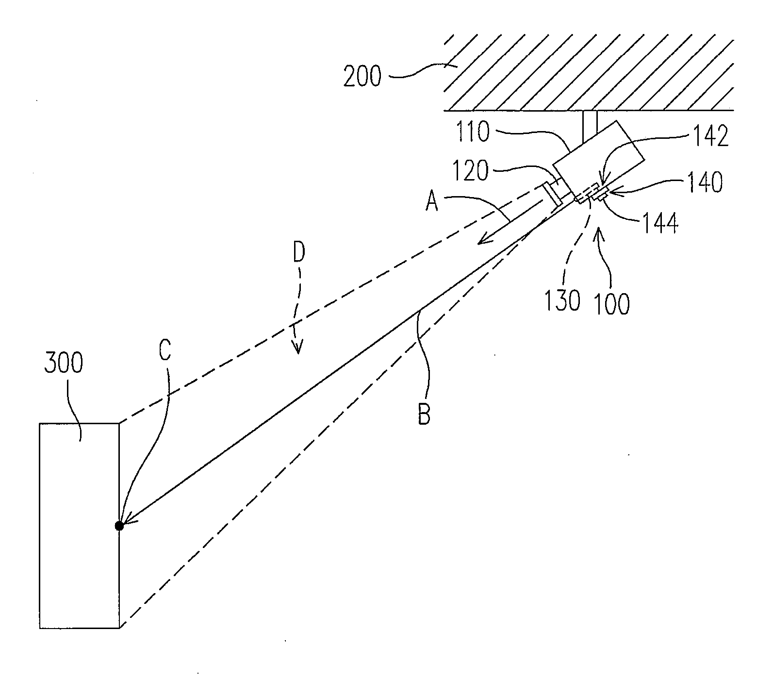
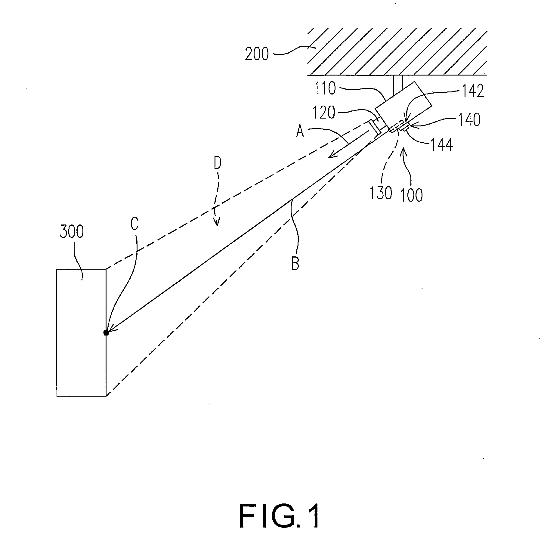
[0021]FIG. 1 is a schematic diagram illustrating a surveillance camera fixed to an object, according to an embodiment of the present invention. Referring to FIG. 1, a surveillance camera 100 of the present embodiment is adapted to be installed onto an object 200. The object 200 for example can be a building, a wall, a ceiling, a post, a ground, or anything suitable for supporting the surveillance camera 100. In this preferred embodiment, the object 200 is exemplified as a ceiling. The surveillance camera 100 includes a housing 110, a monitoring lens 120, and a light beam sight 130.

[0022]The monitoring lens 120 is fixed to the housing 110, and is configured to monitoring toward a monitoring direction ...


PUM


Abstract

A surveillance camera including a housing, a monitoring lens and at least a light beam sight is provided. The monitoring lens is fixed in the housing and faces a monitoring direction. The light beam sight is fixed to the housing and disposed nearby the monitoring lens. The light beam sight is adapted to emit a light beam along the monitoring direction. The light beam is adapted to provide an image fixing position for monitoring lens to fix on an image.

Description

CROSS-REFERENCE TO RELATED APPLICATION[0001]This application claims the priority benefit of Taiwan application serial no. 95136698, filed Oct. 3, 2006. All disclosure of the Taiwan application is incorporated herein by reference.BACKGROUND OF THE INVENTION[0002]1. Field of the Invention[0003]The present invention generally relates to a surveillance system, and more particularly, to a surveillance system with light beam positioning function, and a surveillance camera thereof.[0004]2. Description of Related Art[0005]A surveillance camera is usually secured on a wall or a building, for monitoring internal public areas or surroundings of the building. Such a surveillance camera is generally employed in a surveillance system. The surveillance system generally includes a plurality of surveillance cameras, a surveillance host and a monitor. Typically, the surveillance host is electrically coupled to the surveillance cameras and the monitor. The surveillance cameras convert captured images ...

Claims


Application Information

Patent Timeline
Patent Type & Authority Applications(United States)
IPC IPC(8): H04N7/18H04N9/47
CPCG08B13/19634G08B13/196
Inventor CHANG, CHING-SHAN
Owner APPRO TECH
Why Eureka
Try Eureka