
Wearable data acquisition device

a data acquisition device and wearable technology, applied in the field of wearable devices, can solve the problem of not allowing ambidextrous operation of the data acquisition devi

Inactive Publication Date: 2008-04-03
SYMBOL TECH INC
View PDF7 Cites 33 Cited by
  • Summary
  • Abstract
  • Description
  • Claims
  • Application Information

AI Technical Summary

Problems solved by technology

In addition, a triggering mechanism is also integral with the housing and does not allow for ambidextrous operation of the data acquisition device.

Method used


Image

  • Wearable data acquisition device
  • Wearable data acquisition device
  • Wearable data acquisition device

Examples


Embodiment Construction

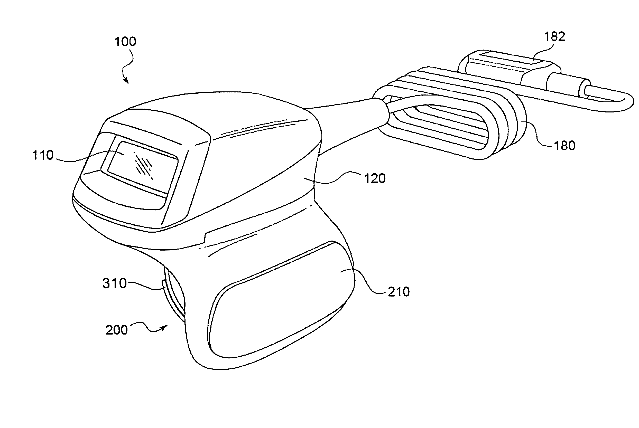
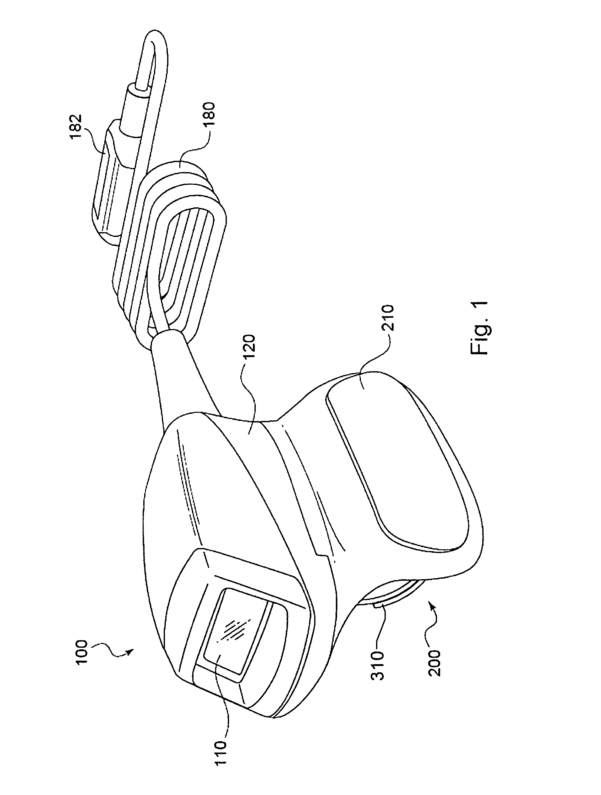
[0008]The present invention may be further understood with reference to the following description and the appended drawings, wherein like elements are provided with the same reference numerals. The present invention relates to wearable data acquisition devices. An exemplary embodiment of the present invention is described with reference to a ring scanner, however those skilled in the art will understand that the present invention may be implemented with any type of wearable data acquisition device, such as a wrist-mounted scanner, a glove scanner, etc. It will also be understood that the present invention is not limited to barcode scanners, but may also include RFID readers, laser- / image-based scanners, card readers and other types of data acquisition devices.

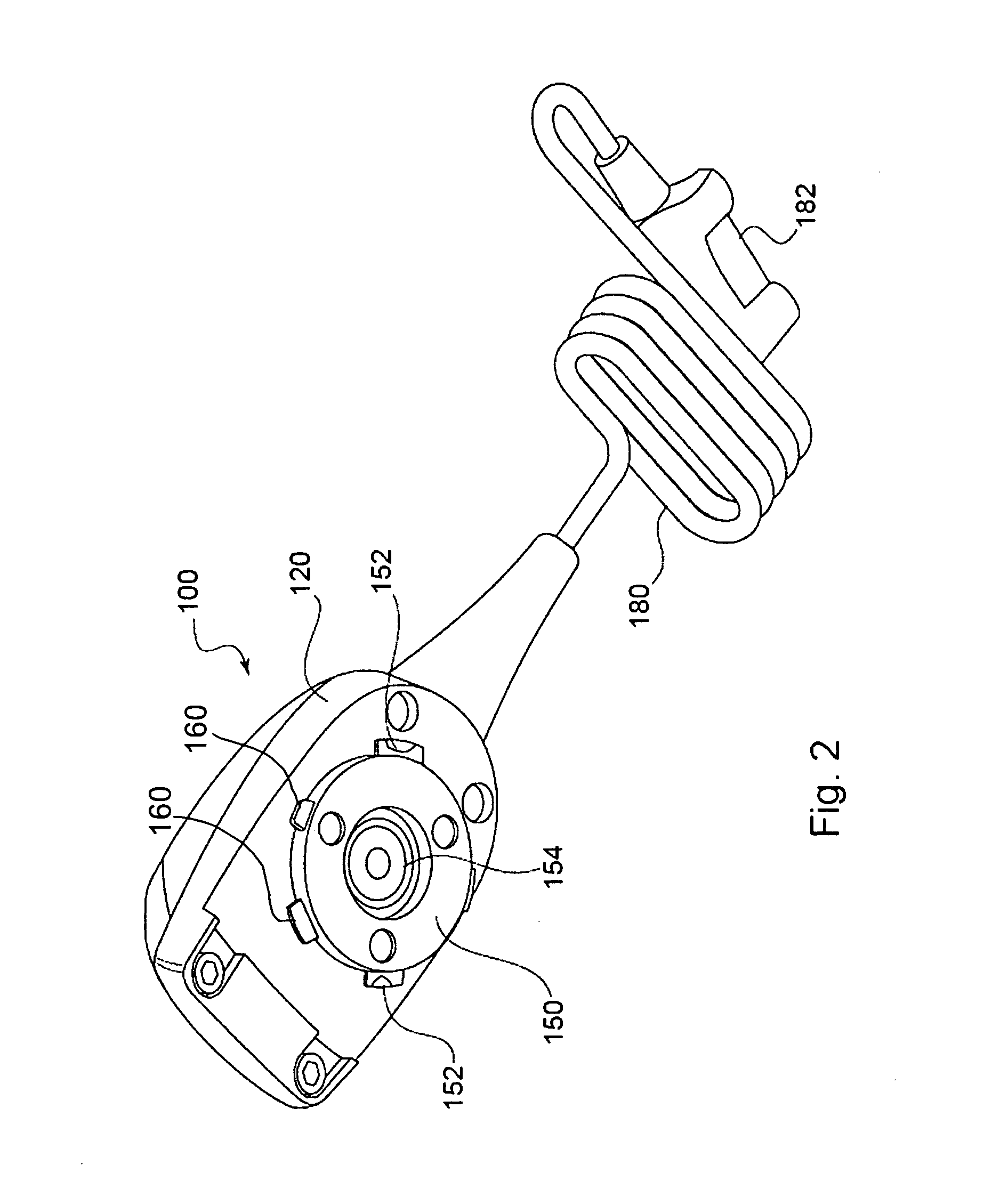
[0009]FIG. 1 shows an exemplary embodiment of a data acquisition device (e.g., a ring scanner) 100 according to the present invention. The scanner 100 includes a housing assembly (e.g., a housing unit 120), which comprises a sc...


PUM


Abstract

A wearable data acquisition device includes (i) a housing unit having a data acquisition arrangement and a base portion. The base portion includes a connector and a triggering area. The device also includes (ii) a trigger unit worn by a user. The trigger unit has a triggering mechanism for engaging the triggering area and a receiving arrangement adapted to receive the connector in an attached configuration. When in the attached configuration, the housing is rotatable about an axis substantially perpendicular to a bottom surface of the base portion.

Description

FIELD OF THE INVENTION[0001]The present invention generally relates to wearable devices and, in particular, to wearable data acquisition devices.BACKGROUND INFORMATION[0002]Conventional wearable data acquisition devices, such as ring scanners, often include an attachment arrangement integrally coupled to a housing thereof. The attachment arrangement is non-removable. In addition, a triggering mechanism is also integral with the housing and does not allow for ambidextrous operation of the data acquisition device. If the attachment arrangement or the trigger mechanism break, the entire device must be replaced.SUMMARY OF THE INVENTION[0003]The present invention relates to a wearable data acquisition device which includes (i) a housing unit having a data acquisition arrangement and a base portion. The base portion includes a connector and a triggering area. The device also includes (ii) a trigger unit worn by a user. The trigger unit has a triggering mechanism for engaging the triggerin...

Claims


Application Information

Patent Timeline
IPC IPC(8): G06K7/10G06K7/00
CPCG06K7/10891G06K7/10881
Inventor MORRIS, QUINTINLIAO, ROBERT
Owner SYMBOL TECH INC
Learn More