
Protector for rock bit seals

Active Publication Date: 2008-03-27
BAKER HUGHES INC
View PDF13 Cites 14 Cited by
  • Summary
  • Abstract
  • Description
  • Claims
  • Application Information

AI Technical Summary

Benefits of technology

[0034]The invention has significant advantages. The protector provides protection against debris contact with elastomeric seal nip areas. The protector does not require any additional seal gland space. The additional protection provided by the protector prolongs the life of the seal and thus the life of the drill bit.

Problems solved by technology

In drilling service, debris, whether it originates from the bearing or the bore hole, might find its way to the seal and cause wear.
The accumulated debris causes wear and leakage.
The secondary seal takes up precious space, and the assembly requires pressure compensation for the space between the two seals.

Method used


Image

  • Protector for rock bit seals
  • Protector for rock bit seals
  • Protector for rock bit seals

Examples


Embodiment Construction

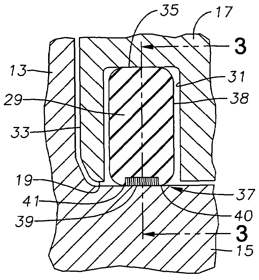
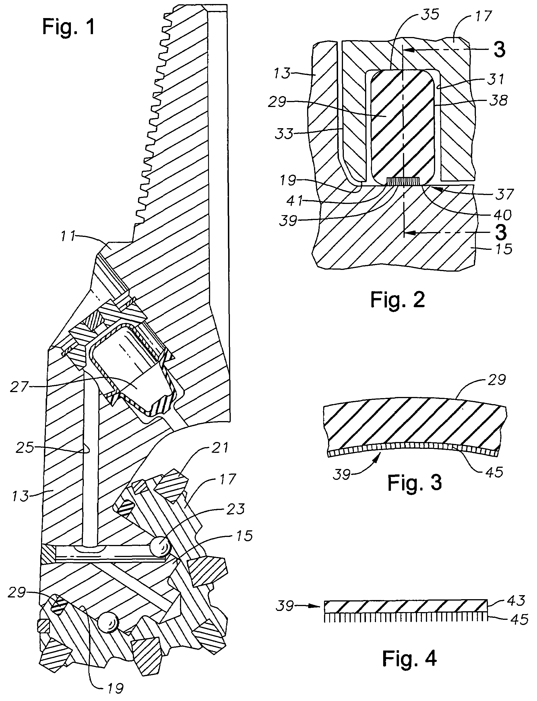
[0019]Referring to FIG. 1, the bit has a bit body 11 with at least one bit leg 13, and preferably three. A bearing pin 15 depends downward and forward from each bit leg 13 toward the bit axis of rotation. A cone 17 has a cavity 19 that slides over bearing pin 15, allowing cone 17 to rotate relative to bearing pin 15. Cone 17 has a plurality of cutting elements 21 on its exterior. Cutting elements 21 may be tungsten carbide inserts pressed into mating holes, or cutting elements 21 may comprise teeth integrally machined from the body of cone 17. Cone 17 is held on bearing pin 15 by a locking element, which in this embodiment comprises a plurality of balls 23 located in mating annular grooves of bearing pin 15 in cone cavity 19.

[0020]A lubricant passage 25 extends through each bit leg 13 from a compensator 27 to the bearing spaces within cavity 19. A seal 29 seals lubricant within the bearing spaces. Compensator 27 reduces the pressure differential across seal 29, which is exposed to b...


PUM


Abstract

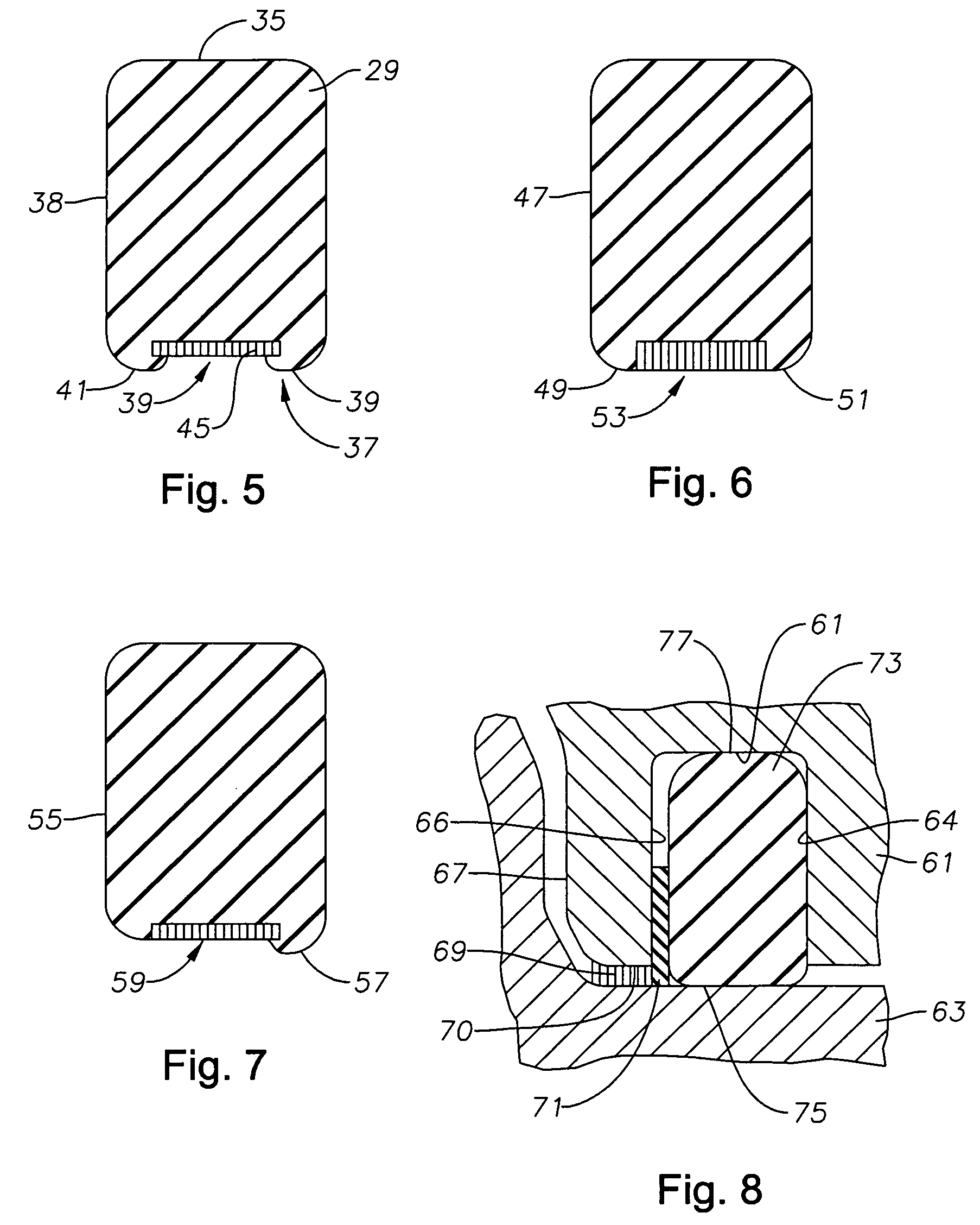
An earth-boring bit has a bit body with a depending bearing pin and a cone rotatably mounted thereon. A seal seals between the bearing pin and the cone. An annular set of bristles is located adjacent at least part of the dynamic seal surface of the seal to protect the seal against debris.

Description

FIELD OF THE INVENTION [0001]This invention relates in general to earth-boring rotary cone drill bits and in particular to a protective device for protecting the seal for each cone from damage due to debris.BACKGROUND OF THE INVENTION [0002]An earth-boring bit of the type concerned herein has a bit body with at least one bearing pin, normally three, and a cone rotatably mounted to each bearing pin. Each cone has cutting elements for disintegrating the earth formation as the bit body rotates. The bearing spaces between the cavity of the cone and the bearing pin are filled with a lubricant. A seal is located near the mouth of the cone cavity for sealing lubricant from drilling fluid.[0003]In drilling service, debris, whether it originates from the bearing or the bore hole, might find its way to the seal and cause wear. One type of seal comprises an elastomeric member with an inner diameter in sliding engagement with the bearing pin and an outer diameter that is normally in static enga...

Claims


Application Information

Patent Timeline
IPC IPC(8): E21B10/22
CPCE21B10/22
Inventor LIN, CHIH C.
Owner BAKER HUGHES INC
Learn More