
Faucet Spray Control Assembly

a control assembly and faucet technology, applied in the field of faucets, can solve the problems of requiring extra room for the faucet on the counter top, affecting the operation of the faucet, and the assembly of pull-out faucets is usually more complicated than conventional faucets, and the arrangement is rather complex

Active Publication Date: 2008-03-20
KOHLER CO
View PDF37 Cites 73 Cited by
  • Summary
  • Abstract
  • Description
  • Claims
  • Application Information

AI Technical Summary

Benefits of technology

[0011]The present invention provides a spray control assembly for a faucet having a faucet body and a spray head in communication with a water line. The spray assembly has a hollow spray head body holding a valve body and an outlet. The valve body has an axial valve cavity where the diverter valve can slide along a valve axis to seat and un

Problems solved by technology

However, these faucets require extra room on the counter top for the sprayer mounting, as well as a separate hole through the counter top.
Assembly of such pull-out faucets is usually more complicated then conventional faucets due to the added valve and spray control hardware required to be packed in the faucet.
This arrangement is rather complex and is susceptible to incomplete or inconsistent actuation of the valve if the toggle does not move into the proper position following the previous actuation.

Method used


Image

  • Faucet Spray Control Assembly
  • Faucet Spray Control Assembly
  • Faucet Spray Control Assembly

Examples


Embodiment Construction

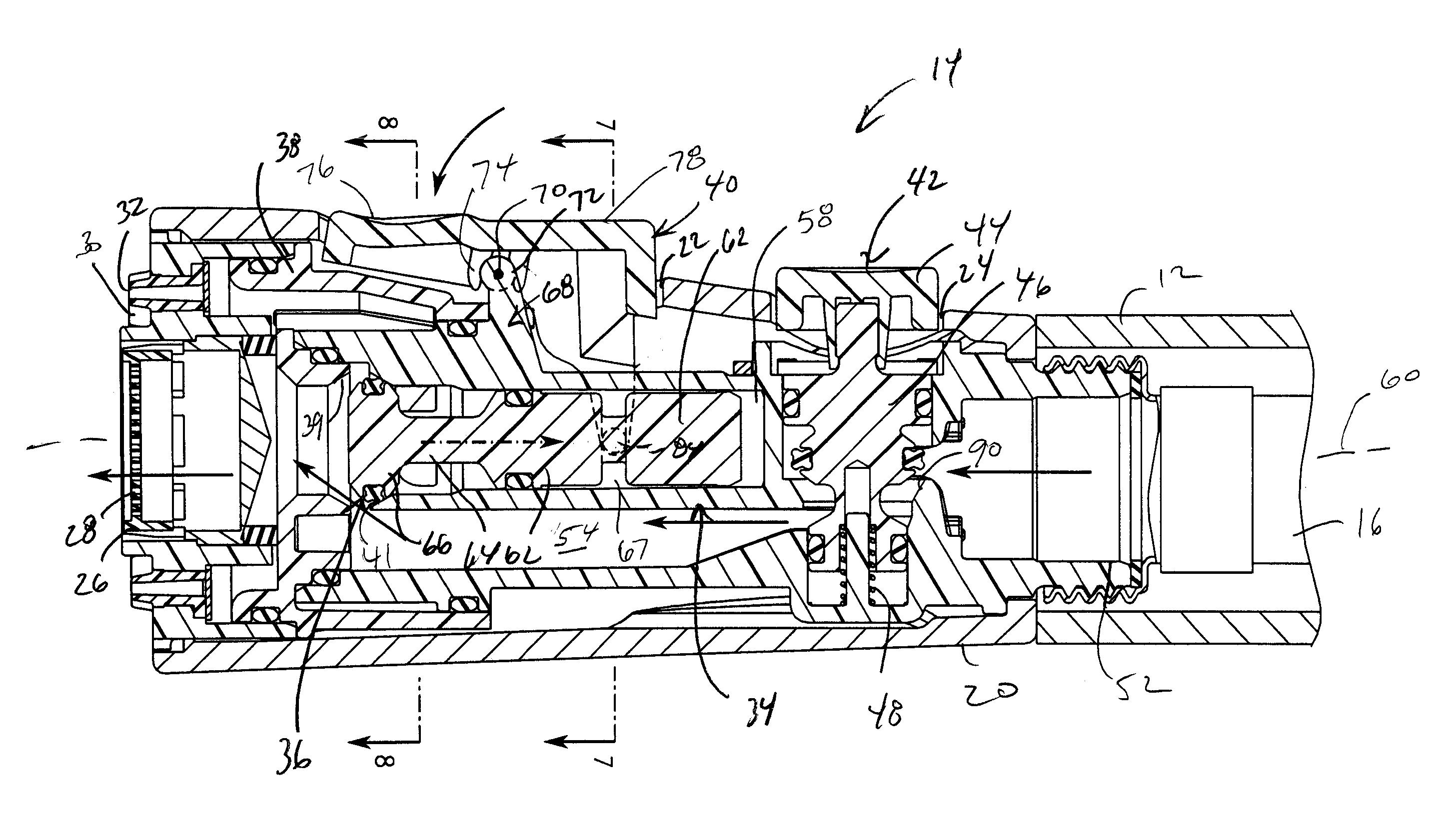
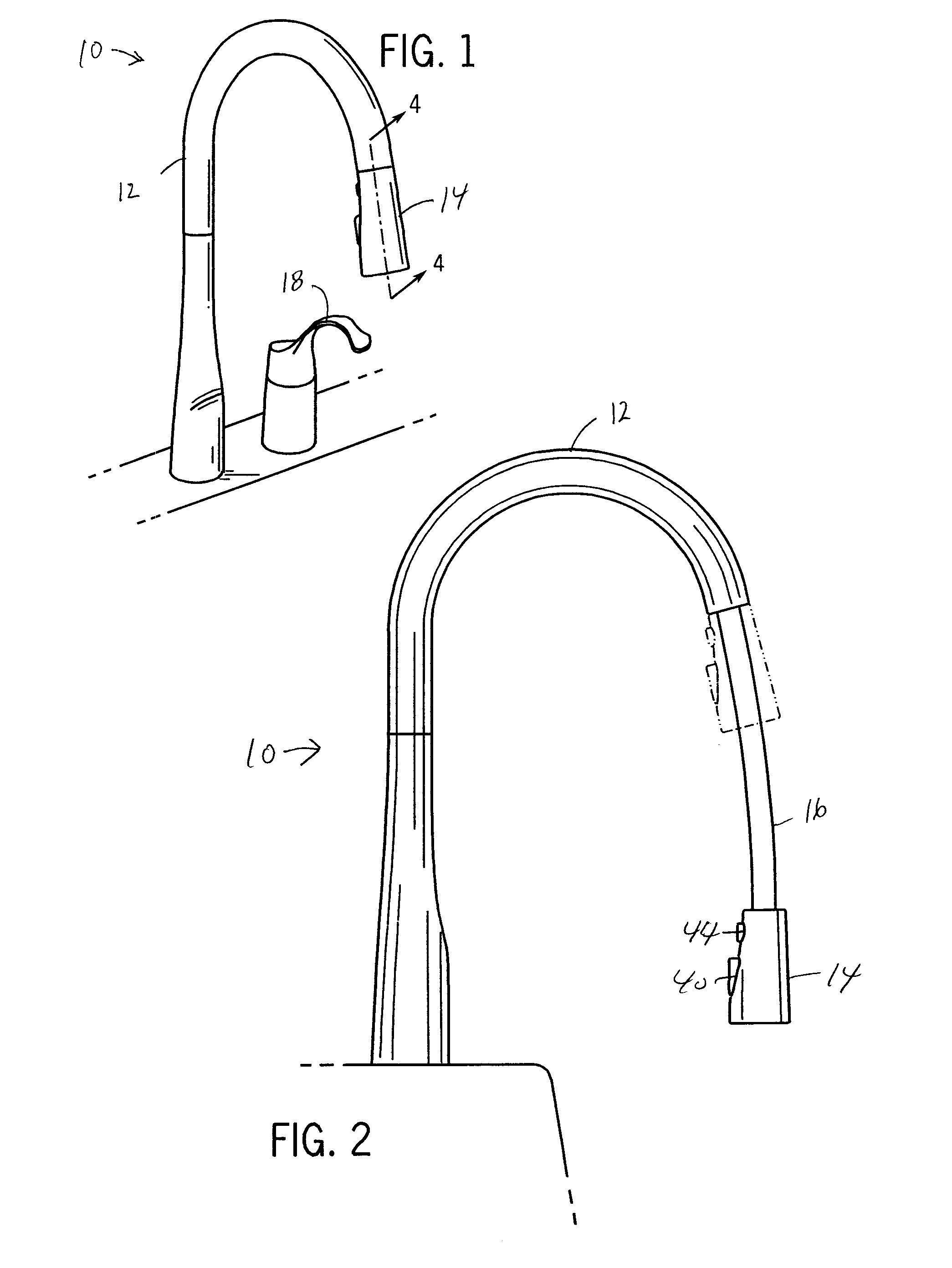
[0026]FIG. 1 shows a preferred version of a pull-out faucet 10 having a cane-shaped spout body 12 and a spray head 14. As shown in FIG. 2, the faucet's spray head 12 can be pulled, in this case downwardly at first, from the retracted position shown in FIG. 1 to an extended position. The faucet 10 can thus be used as a conventional faucet in which the spray head 14 is mounted to the spout 12, or with the spray head 14 separated from the spout 12 to be moved freely, limited only by the length of the attached spray hose 16 connected via a primary valve to water inlet line(s) of the building's plumbing system.

[0027]Any water mixing components of the spout 14 and the weighted flexible lines that provide for the pull-out feature of the faucet 10 can be generally of the type disclosed in U.S. Pat. No. 6,757,921, hereby incorporated by reference as though fully disclosed herein, and are commercially available from Kohler Company of Kohler, Wis. Briefly, as is conventional, the faucet 10 can...


PUM


Abstract

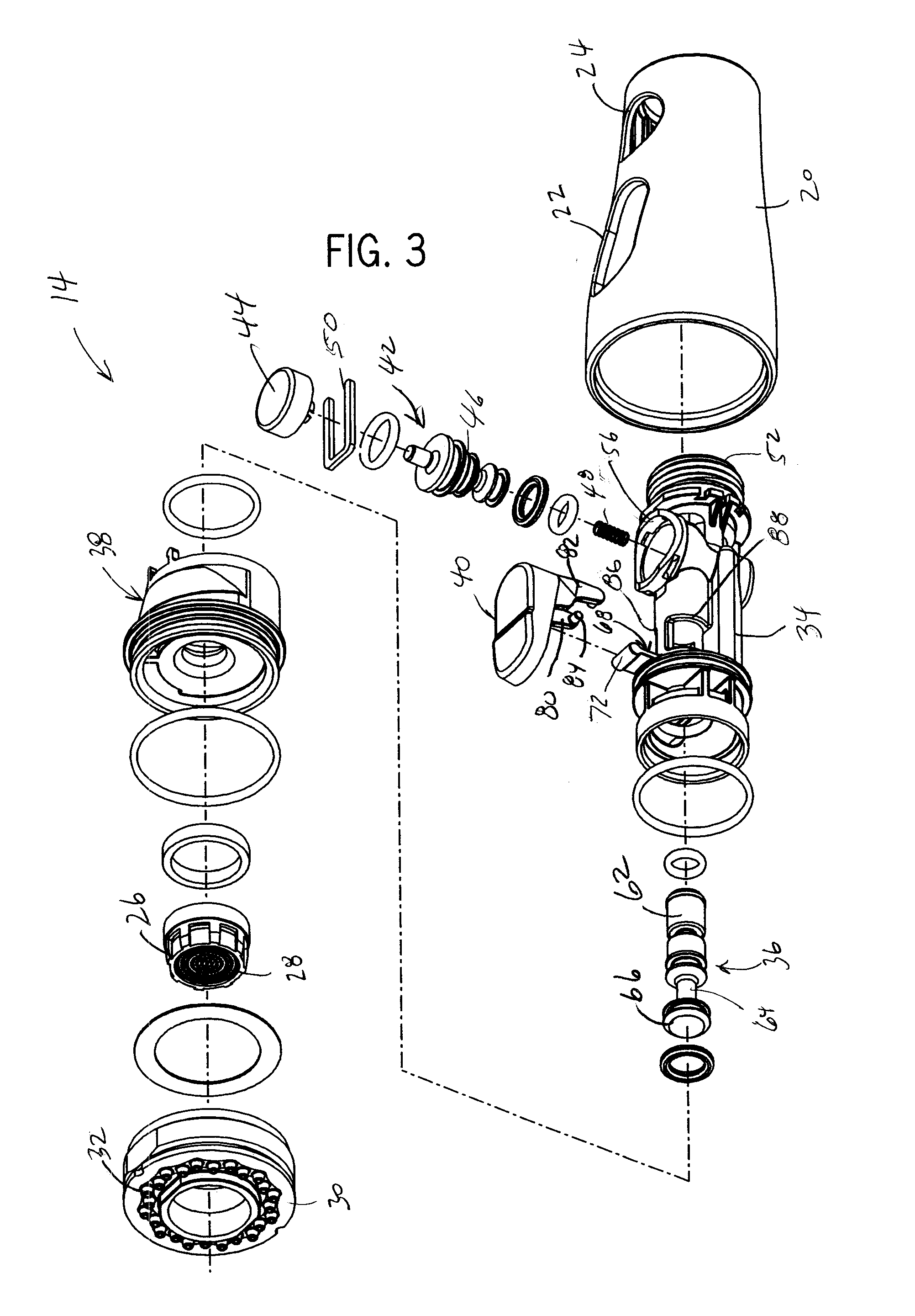
A pull-out faucet has a spray head with spray selection and pause control. A spring-loaded push button interrupts outlet spray entirely as long as it is being depressed. A rocker button controls spray through inner and outer sets of outlet orifices, for example, giving the user the option of an aerated water jet or an unaerated shower. The rocker button mounts on an integral pivot post of a valve body that houses a diverter valve that is controlled by the rocker button. The rocker button has a pair of legs that extend through openings in the valve body to engage a groove in the diverter valve. Pivoting the rocker button about a pivot axis by depressing either its forward or aft portion, moves the diverter valve along a valve axis to route flow to either the inner or outer orifices.

Description

CROSS-REFERENCE TO RELATED APPLICATION[0001]Not applicable.STATEMENT OF FEDERALLY SPONSORED RESEARCH OR DEVELOPMENT[0002]Not applicable.BACKGROUND OF THE INVENTION[0003]The present invention relates to faucets, and in particular to faucets with spray heads providing spray control.[0004]Conventional faucets have a faucet body, one or more flow control / mixing valves, one or more control handles, and a spout. The spout acts a conduit for expelling water that has passed through the valve(s), in which case the outflow is either fixed to begin at a single point, or in the case of a pivotal spout is limited to begin over a range of a prescribed horizontal arc.[0005]Faucets have conventionally been provided with separate stand-alone hand-held sprayers to provide the user with more flexibility with regard to the direction and point that outflow begins, particularly to facilitate spraying down dishware. These sprayers have a flexible hose attached to the spray head allowing the spray head to ...

Claims


Application Information

Patent Timeline
IPC IPC(8): A62C31/00B05B9/01
CPCB05B1/1618B05B1/18B05B1/3013E03C2001/0415E03C1/0404E03C1/0405B05B12/002Y10T137/9464
Inventor ERICKSON, PERRY D.HANSEN, DAVID E.MONTAG, PATRICK H.
Owner KOHLER CO
Learn More