Dual-Chamber Type Oil Pan and Engine Equipped with Same
a dual-chamber, oil pan technology, applied in the direction of machines/engines, mechanical equipment, transportation and packaging, etc., can solve the problem that engine oil is not suitable for circulation, and achieve the effect of high viscosity, rapid rise, and effective prevention of sucking
- Summary
- Abstract
- Description
- Claims
- Application Information
AI Technical Summary
Benefits of technology
Problems solved by technology
Method used
Image
Examples
first embodiment
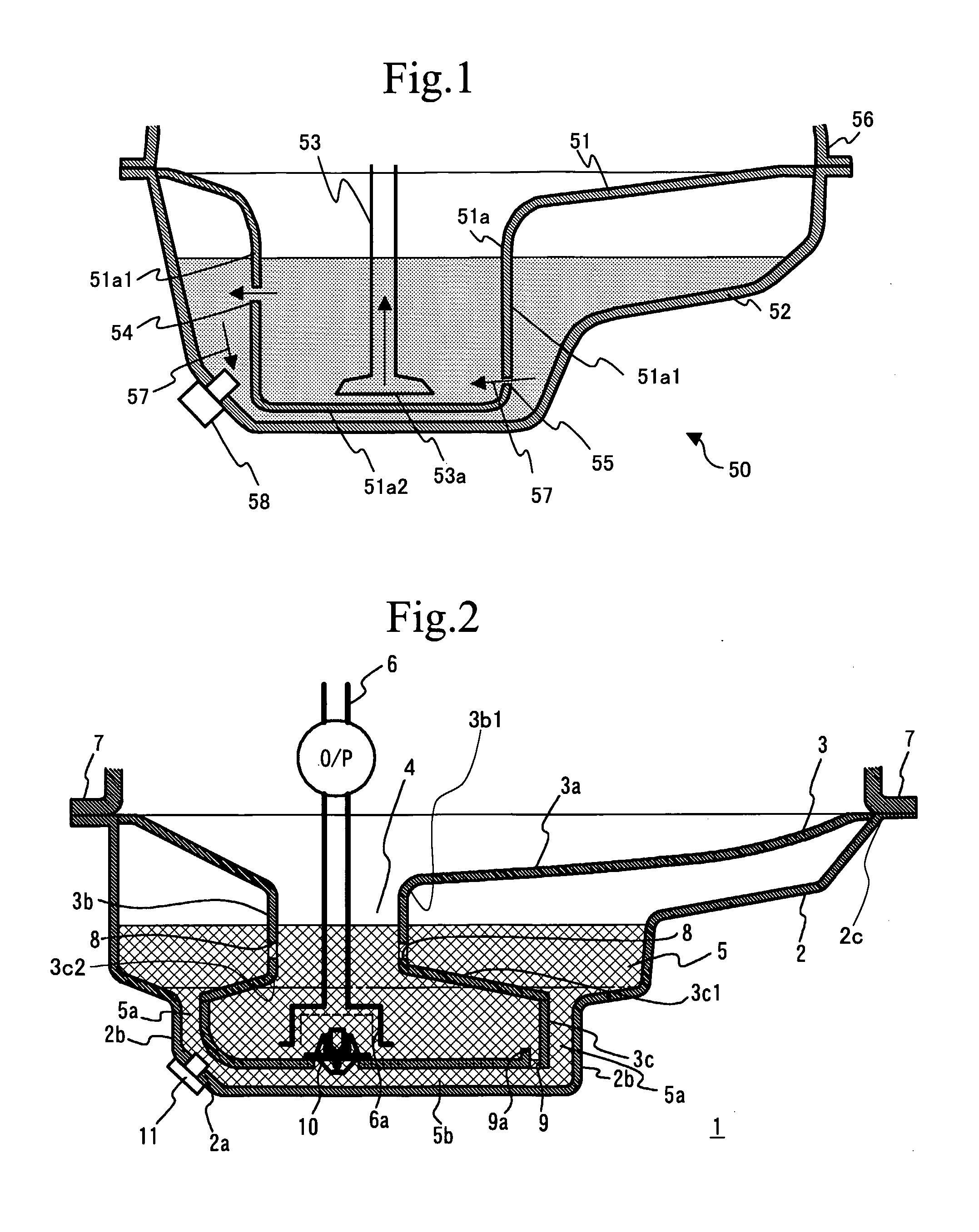
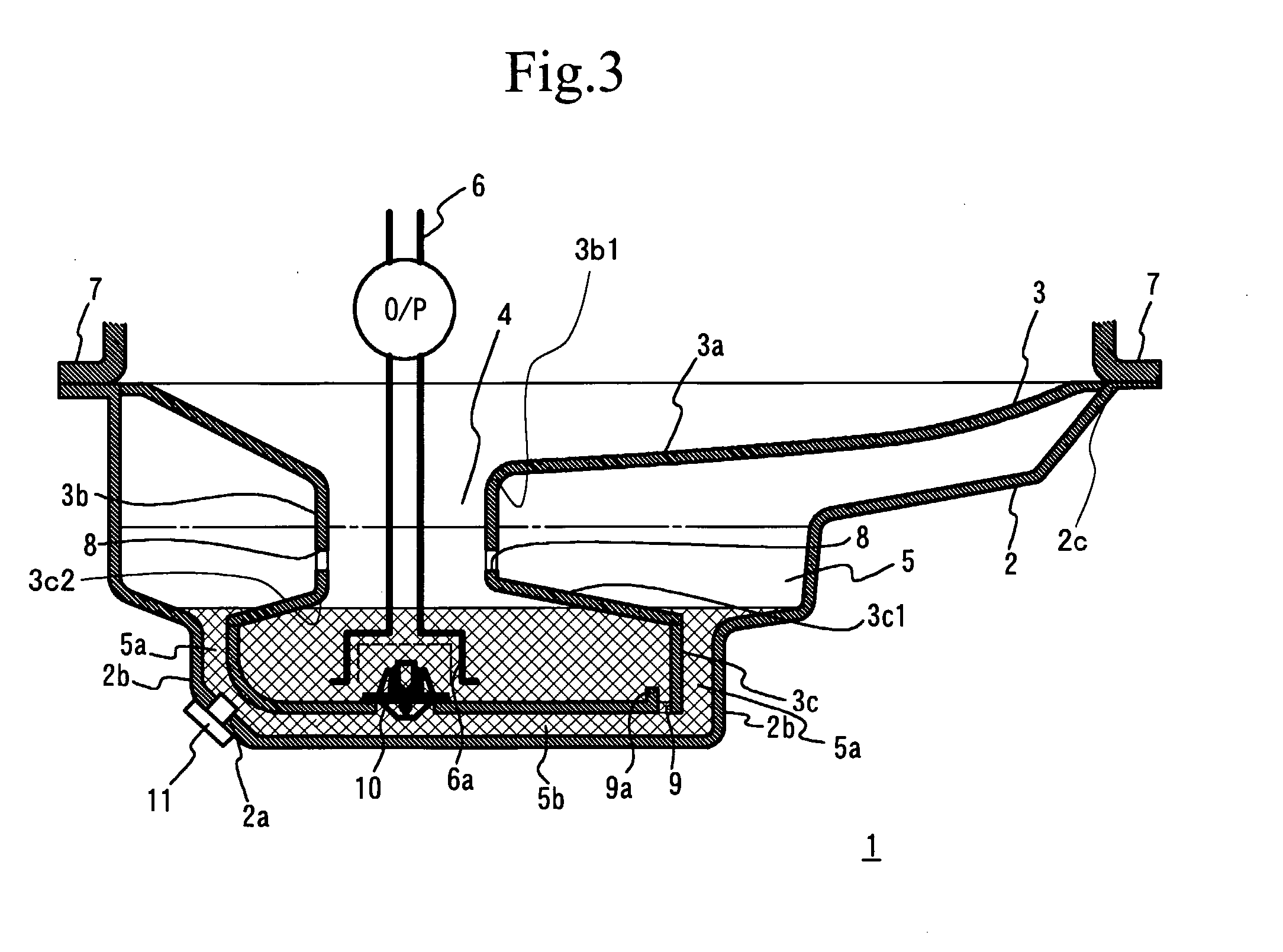
[0041] A dual-chamber oil pan in accordance with a first embodiment of the present invention will now be described. FIGS. 2 and 3 are respectively cross-sectional views of a dual-chamber oil pan 1 in according with the first embodiment of the present invention. More specifically, FIG. 2 shows a state in which engine oil stored is up to a given level prior to engine start, and FIG. 3 shows another state in which some engine oil has been supplied to an engine block 7 from the dual-chamber oil pan 1 and the remaining engine oil in the dual-chamber oil pan 1 is thus reduced. The dual-chamber oil pan 1 is attached to a lower portion of the engine block 7, and is equipped with an oil pan separator arranged within an oil pan 2. The oil pan separator 3 defines a first chamber 4 and a second chamber 5 within the oil pan 2. The first chamber 4 communicates with the inside of the engine block 7. The second chamber 5 is arranged so as to cover or surround the first chamber 4, and is located aro...
second embodiment
[0053] A description will now be given, with reference to FIGS. 5 through 7, of a second embodiment of the present invention. A dual-chamber oil pan 20 in accordance with the second embodiment differs from the dual-chamber oil pan 1 of the first embodiment as follows. An oil pan separator 23 provided in an oil pan 22 of the dual-chamber oil pan 20 has a narrowed portion 23d in addition to an oil receiving portion 23a, a small-capacity portion 23b and a large-capacity portion 23c as those of the oil pan separator 3 of the dual-chamber oil pan 1. The suction port 6a is disposed within the narrowed portion 23d. Further, an eaves-like plate 24 is provided above the suction portion 6a.
[0054] In the dual-chamber oil pan 20 thus structured, the suction port 6a may be placed more deeply than that in the dual-chamber oil pan 1 of the first embodiment by a depth equal to the length of the narrowed portion 23d. This structure secures an increased distance between the oil level and the suction...
third embodiment
[0058] A description will now be given, with reference to FIGS. 8 through 10, of a third embodiment of the present invention. FIG. 8 is a plan view of a dual-chamber oil pan 30 in accordance with the third embodiment, and FIG. 9 is a cross-sectional view taken along a line A-A shown in FIG. 8. FIG. 10 is a cross-sectional view taken along a line B-B shown in FIG. 8. Referring to these figures, a dual-chamber oil pan 30 has an oil pan separator 33 provided in an oil pan 32. The oil pan separator 33 divides the inner area of the oil pan 32 into the first chamber 4 communicating with the engine block 7 and the second chamber 5 arranged so as to cover the first chamber 4. This structure of the oil pan separator 33 is the same as that of the dual-chamber oil pan 1 of the first embodiment.
[0059] The first chamber 4 includes a large-capacity portion 33c provided on the bottom side of the oil pan separator 33, and a small-capacity portion 33b that is connected to the large-capacity portion...
PUM
 Abstract
Description
Claims
Application Information
 - R&D
- Intellectual Property
- Life Sciences
- Materials
- Tech Scout
- Unparalleled Data Quality
- Higher Quality Content
- 60% Fewer Hallucinations
Browse by: Latest US Patents, China's latest patents, Technical Efficacy Thesaurus, Application Domain, Technology Topic, Popular Technical Reports.
© 2025 PatSnap. All rights reserved.Legal|Privacy policy|Modern Slavery Act Transparency Statement|Sitemap|About US| Contact US: help@patsnap.com


