
Drum for a production unit for a non-woven material, method for production of a non-woven material and non-woven material obtained thus

Active Publication Date: 2008-03-20
RIETER PERFOJET
View PDF26 Cites 2 Cited by
  • Summary
  • Abstract
  • Description
  • Claims
  • Application Information

AI Technical Summary

Benefits of technology

[0004] The invention remedies this disadvantage by making it possible to obtain a nonwoven material whose properties are subs

Problems solved by technology

This method has the disadvantage of adversely affecting the uniformity of the formation of the material and

Method used


Image

  • Drum for a production unit for a non-woven material, method for production of a non-woven material and non-woven material obtained thus
  • Drum for a production unit for a non-woven material, method for production of a non-woven material and non-woven material obtained thus
  • Drum for a production unit for a non-woven material, method for production of a non-woven material and non-woven material obtained thus

Examples


Example

DETAILED DESCRIPTION OF THE DRAWINGS

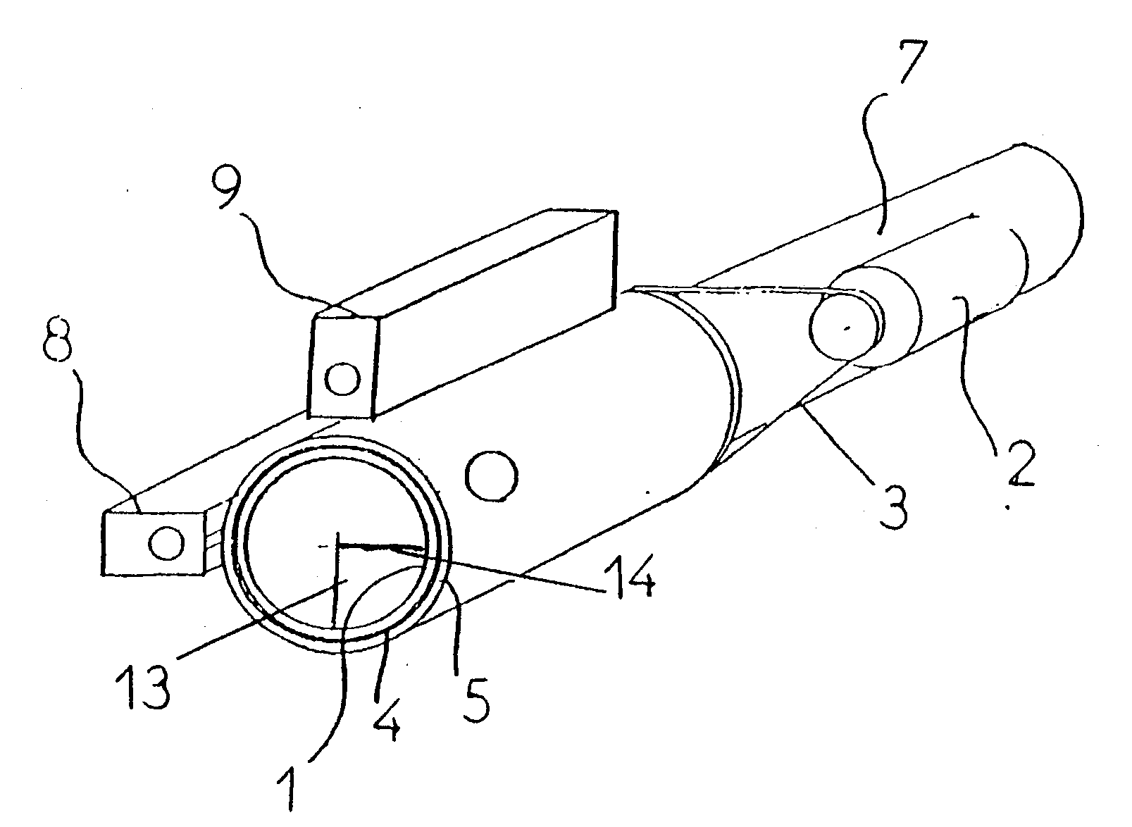
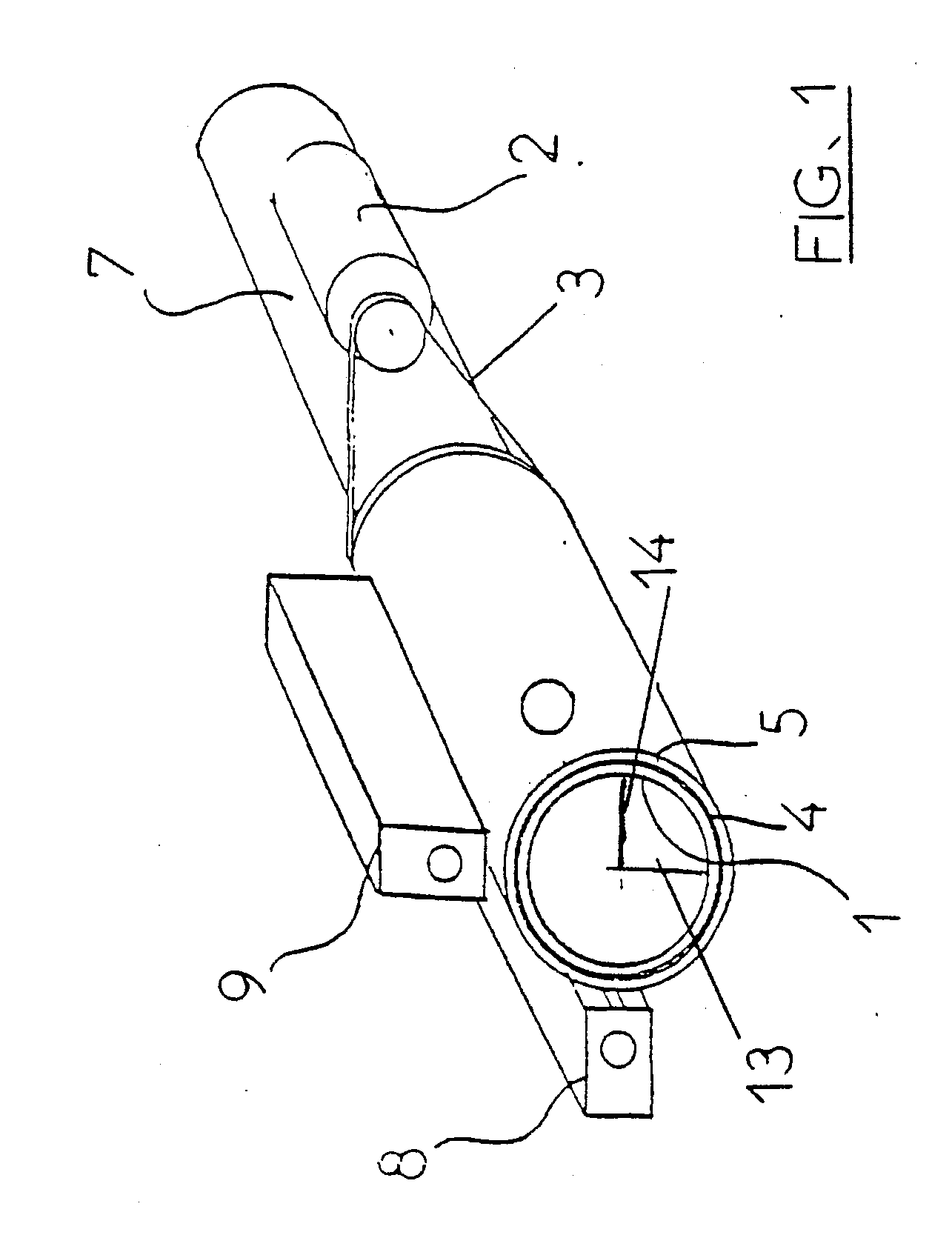
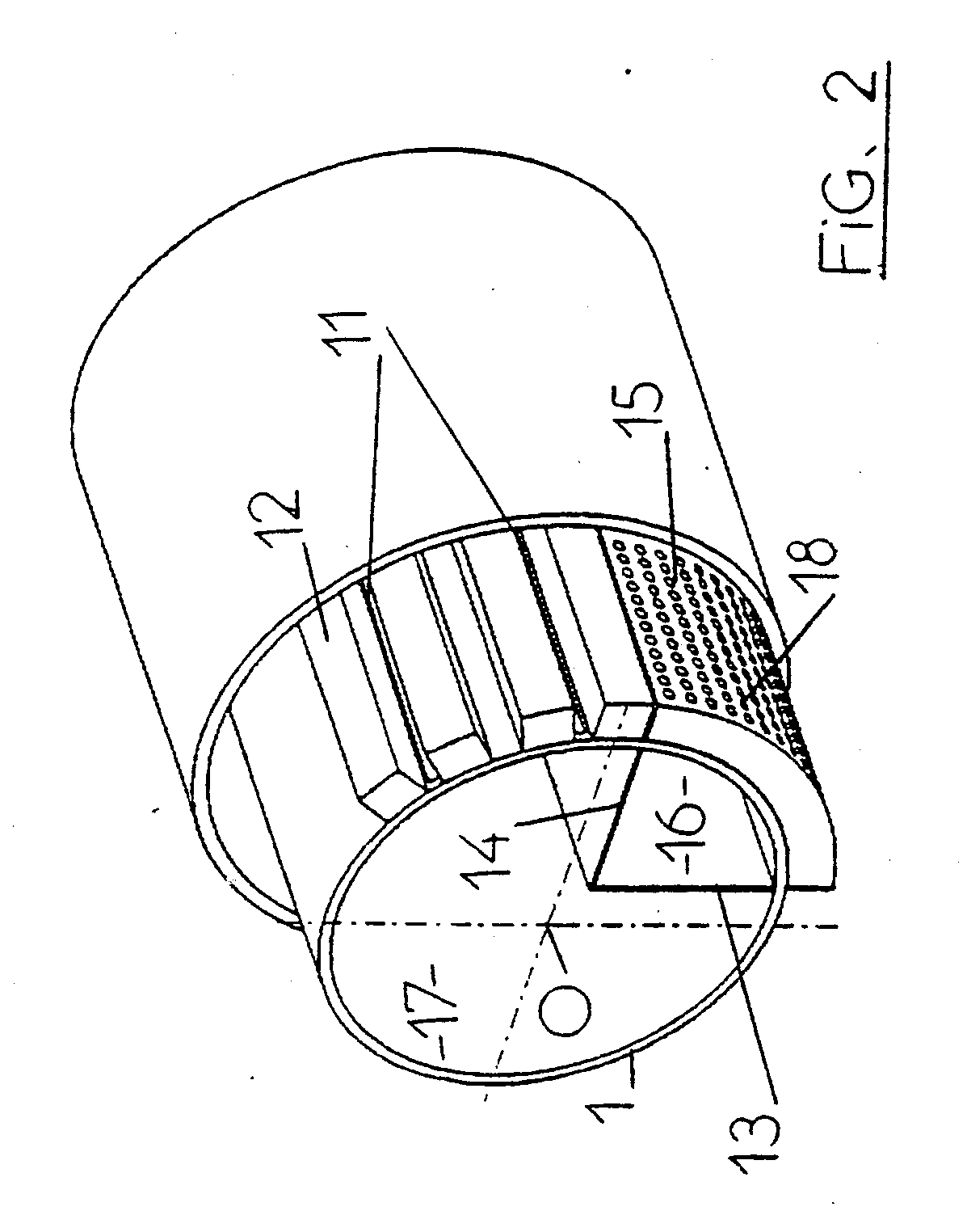
[0022] The drum represented schematically in FIG. 1 comprises an internal body 1 consisting of a fixed roll with a diameter of 400 mm and of a metal sheet forming the lateral surface. The lateral surface is perforated with perforations of a diameter of 8 mm in one portion which will delimit what will later be called the first compartment and the lateral surface is pierced with several slots particularly opposite the injectors in a portion which will delimit what will later be called the second compartment. The ratio (void fraction) of the sum of the areas of the perforations to the total lateral surface area is between 5% and 30% in the first compartment and between 2% and 15% in the second compartment. A perforated rotating roll 4 is slipped over the body 1 and is driven in rotation by a belt drive device 2. The roll 4 is holed. The ratio of the sum of the areas of the holes to the total lateral surface area of the roll 4 is between 30% and 90% ...


PUM

PropertyMeasurementUnit
Speedaaaaaaaaaa
Dimensionaaaaaaaaaa
Displacementaaaaaaaaaa

Abstract

A drum for processing nonwovens has a perforated lateral surface and an interior divided into first and second compartments, respectively associated with first and second lateral surface portions of the drum. A partial vacuum in each of the compartments aspirates and secures a tangentially-engaged nonwoven preform against the lateral surface of the drum for further processing. The drum may be incorporated in a production unit or installation including a spunbond tower for spinning filaments to form the nonwoven preform for tangential delivery to the drum. The resulting nonwoven may thereby be provided with uniform properties.

Description

[0001] This application is a division of U.S. application Ser. No. 10 / 510,382, filed Oct. 5, 2004, which is a 371 of International Application PCT / FR03 / 01101, filed Apr. 8, 2003.BACKGROUND OF THE INVENTION AND RELATED ART [0002] The present invention relates to nonwoven materials and their methods and units of production. [0003] U.S. Pat. No. 6,321,425 describes a method of fabricating a nonwoven material which consists in sending a material, originating from a spunbond tower which normally comprises successively from top to bottom a generator of a curtain of filaments, in particular plastic filaments, a slotted attenuator device for drawing the filaments of the curtain, a diffuser and a conveyor for receiving the filaments, to a calendar which consolidates the formed material preform, then to a water jet tangling drum. This method has the disadvantage of adversely affecting the uniformity of the formation of the material and of orienting the filaments preferentially in the machine ...

Claims


Application Information

Patent Timeline
IPC IPC(8): D04H1/46D04H3/11D04H3/16
CPCD04H3/11D04H18/04D04H13/00
Inventor NOELLE, FREDERIC
Owner RIETER PERFOJET
Learn More