
Dc-dc converter and method

a converter and dc technology, applied in the direction of electric variable regulation, process and machine control, instruments, etc., can solve the problems of large stray capacitance, large area consumed by semiconductor materials, and difficult stabilization of negative feedback loop

Active Publication Date: 2008-03-13
SEMICON COMPONENTS IND LLC
View PDF4 Cites 49 Cited by
  • Summary
  • Abstract
  • Description
  • Claims
  • Application Information

AI Technical Summary

Problems solved by technology

Stabilizing the negative feedback loop is difficult because it includes an inductor and shunt capacitor and operates with a wide range of load currents.
However, they use many high valued resistors to limit the current of the controller circuits.
In addition, manufacturing high valued resistors using CMOS technology consumes large areas of the semiconductor material.
The use of large areas also introduces large stray capacitances, which are undesirable because they lower the switching speeds and increase power consumption of the CMOS devices.

Method used


Image

  • Dc-dc converter and method
  • Dc-dc converter and method
  • Dc-dc converter and method

Examples


Embodiment Construction

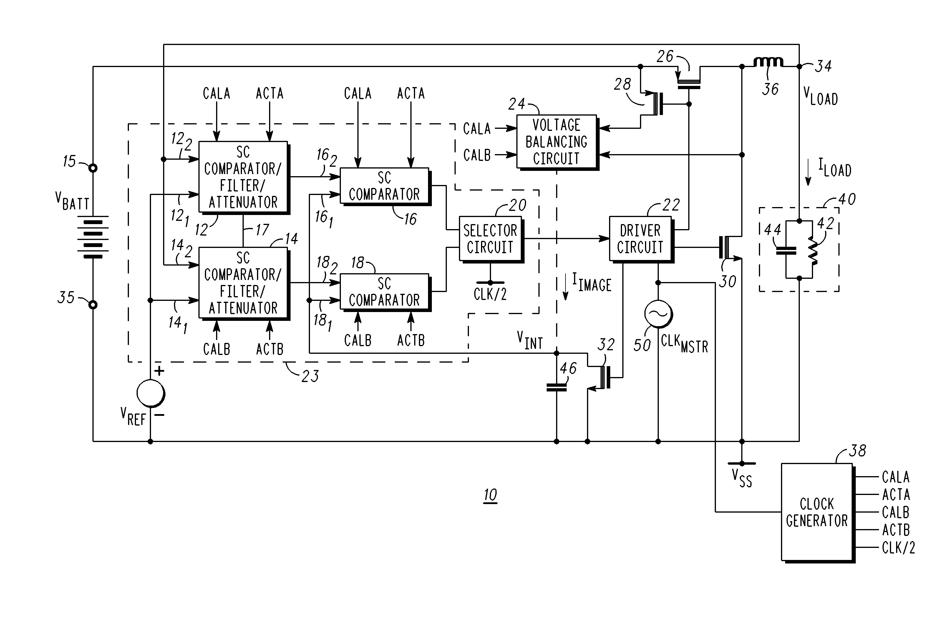
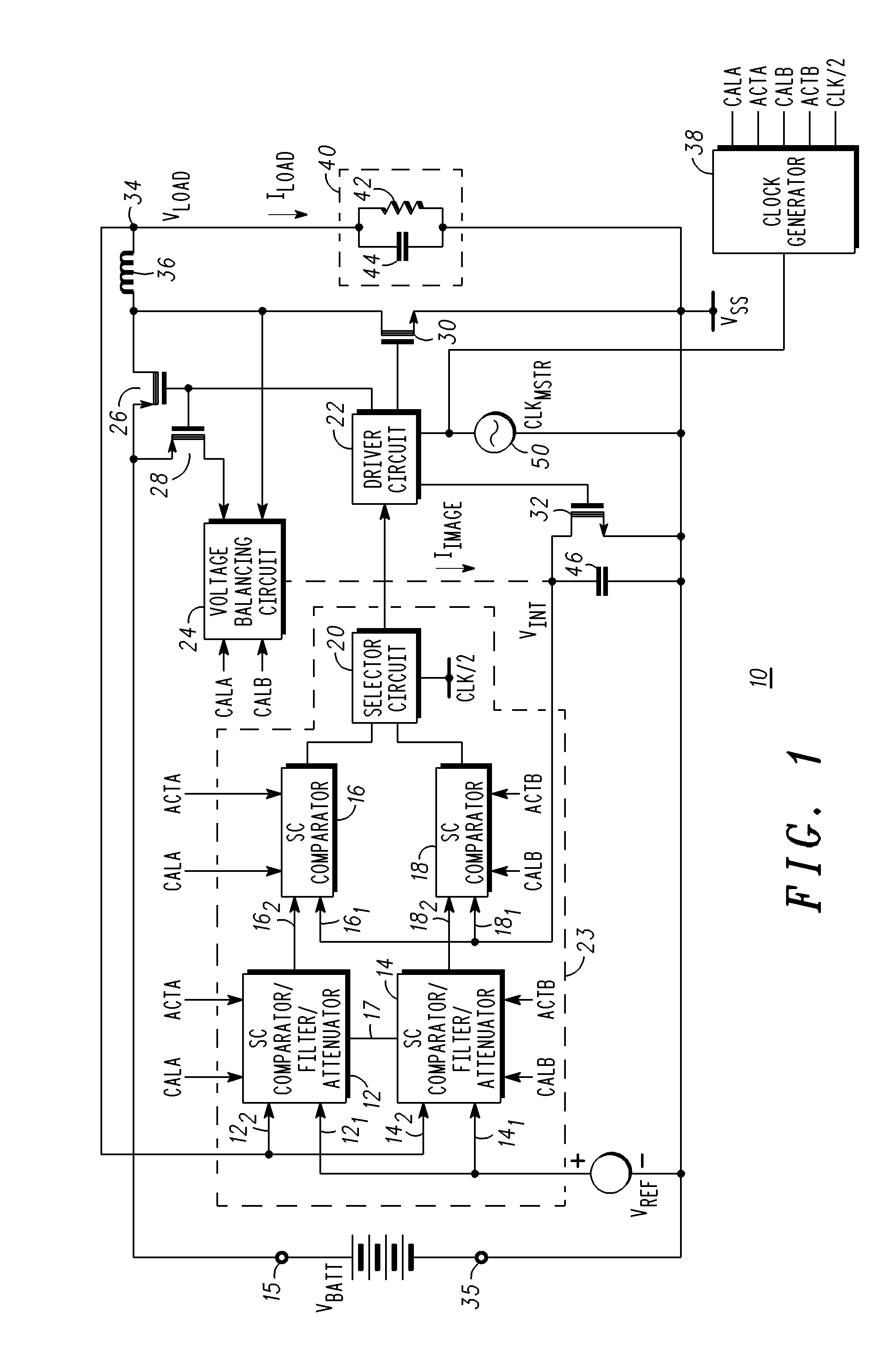
[0016]Generally, the present invention provides a switching Direct Current-Direct Current (“DC-DC”) converter capable of receiving an input voltage VBATT from a battery and providing a regulated output voltage that has a lower voltage level. In accordance with one embodiment, the invention comprises a DC-DC converter that has an inductor having one terminal coupled for receiving an input power signal through a plurality of switches and the other terminal coupled to a load. The switches are repetitively operated at a desired clock frequency and have commutation instants that are responsive to signals derived from a control circuit. The control circuit has two circuit paths each made up of a plurality of circuit elements and adapts a load voltage to have a desired relationship to a reference voltage. The circuit paths are operated such that one or more of the circuit elements of either path may be temporarily switched into an error correction mode while the elements of the other path ...


PUM


Abstract

A DC-DC converter and method for compensating for errors in the DC-DC converter. The DC-DC converter includes an inductor coupled for receiving a source of operating voltage through a plurality of switches. The switches are controlled by a control circuit that has first and second circuit paths that are substantially parallel to each other. Each circuit path is comprised of two switched capacitor comparators that are connected in series. The circuit paths function such that during one portion of a clock period one of the circuit paths operates in an error correction mode and the other circuit path operates in a normal mode. During a different portion of the clock period the operational modes of the circuit paths switch. This allows for a calibration interval in a sampled system in which at least one circuit path is always active and responsive to the input signals in a desired manner.

Description

FIELD OF THE INVENTION[0001]This invention relates, in general, to regulator circuits and, more particularly, to DC to DC converters.BACKGROUND OF THE INVENTION[0002]Battery operated devices such as mobile telephones, portable computers, calculators, cameras, Personal Digital Assistants (PDAs), video game controllers, etc. typically include DC-DC converters to produce a constant power supply voltage at the load. Although a constant voltage is provided at the load, the battery voltage decreases as the battery is discharged. These circuits include switches that alternate connecting an inductor between the battery and a load and between the load and ground using low-loss switches, which are usually operated at a fixed frequency. In other words, the circuits switch the connections such that during one part of the clock period the inductor is connected between the battery and a load and during another part of the clock period the switches connect the inductor between the load and ground....

Claims


Application Information

Patent Timeline
Patent Type & Authority Applications(United States)
IPC IPC(8): H02M3/24
CPCH02M3/156
Inventor GAY, MICHAEL JOHN
Owner SEMICON COMPONENTS IND LLC
Learn More