
Double barrel drinking vessel

a drinking vessel and double-barrel technology, applied in the field of drinking vessels, can solve the problems that the type of drinking vessel does not function to provide a shot and a chaser, but rather an ordinary mixed drink, and achieve the effect of safe sitting on a flat surface, longer and more slender

Inactive Publication Date: 2008-03-06
MORAN CASEY CHRISTOPHER
View PDF7 Cites 8 Cited by
  • Summary
  • Abstract
  • Description
  • Claims
  • Application Information

AI Technical Summary

Benefits of technology

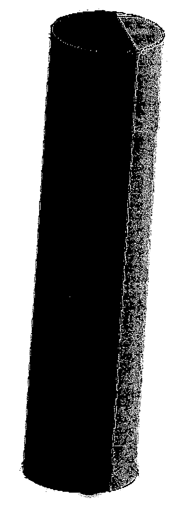
[0012]Our solution to the above mentioned problems associated with other glasses used in the art is the Double Barreled Drinking Vessel. This drinking vessel is similar in overall shape to the test tube style shot glass yet has a divider, flush with the very top of the vessel, forming two separate chambers in a 2:1 ratio. The overall shape is longer and more slender than a traditional shot glass yet flat at the bottom so it can safely sit on a flat surface. The opening at the top of the vessel (mouthpiece) is much smaller in circumference to a regular shot glass so that the mouthpiece is the perfect size to fit into the user's mouth eliminating spills and procuring the end result of the two liquids staying separate until they are actually poured into the mouth.
[0013]This unique shape is superior to the shape of the Quaffer in that it serves a smaller portion of beverages therefore eliminating the issue of choking on or spilling the contents of the shot. It still, however, gives the user the same effect of having a shot with a chaser without having to drink as much as if a Quaffer was used due to the vertical divider separating the two chambers.
[0014]The vertical divider also solves the problems associated with the original test tube shot. Our drinking vessel embodies a long, slender shape such as the test tube shot but also allows the beverages poured to remain separate and not mix until the user decides to drink the shot. This allows for more variation in the combinations of shots that can be prepared. Our vessel also differs from the test tube shot in that it is flat at the bottom. Therefore the user can safely sit the drink on the table and drink it at his or her leisure.
[0016]The “split shot glass” described in the section above is perhaps the closest comparison to the present invention in that the divider in the glass is flush with the top of the glass. However, there are three key differences. First, the aforementioned “split shot glass” is shaped more like a traditional sized shot glass with a wide opening at the top. The wide opening makes it difficult to consume the contents in the glass as a shot because it increases the risk of spilling or liquid seeping out and getting on the user's clothes, face, etc. . . . The present invention's narrow mouthpiece eliminates this problem as it easily fits into the mouth of the drinker leaving no margin for embarrassing spills.
[0017]The second key difference is in the way the two chambers are divided. The “split shot glass” provides a 1:1 ratio between the chambers. This limits the types of shots that can be prepared in this type of vessel because there are very few recipes known in the art where the alcohol and the chaser amounts are exactly equal. The present invention embodies a 2:1 ratio (likely chaser:alcohol) which makes it more versatile and useful for bartenders because the majority of true mixed shots are poured in a 2:1 ratio. This ratio is preferred because it improves the taste of the shot and allows it to go down more smoothly.
[0018]The third difference between these two vessels is the shape of the divider. The “split shot glass” has a curved divider giving an aesthetic swirling effect when liquid is poured into the chambers. Although aesthetically pleasing, this curved divider slows the time that it takes to consume the drink thus dragging out the process of doing the shot. In the present invention the divider is straight. When it is used, the liquid easily flows out of both chambers to combine in the mouth efficiently and smoothly making it a one step process and completely eliminating the chance of having to tip the vessel again to get all the contents.

Problems solved by technology

Thus, these types of vessels do not function to provide a shot and a chaser but rather an ordinary mixed drink.

Method used


Image

  • Double barrel drinking vessel
  • Double barrel drinking vessel
  • Double barrel drinking vessel

Examples


Embodiment Construction

[0021]The present invention is a conical shaped drinking vessel with two separate chambers. One end of the vessel is completely closed forming a flat surface functioning as the bottom of the vessel. The other end of the vessel is open or not enclosed, functioning as the top of the vessel. A dividing wall runs run the entire length of the vessel forming two internal chambers within the vessel. The dividing wall is placed within the walls of the vessel to give the internal chambers a 2:1 volume ratio. The dividing wall is flush with the top and bottom of the vessel giving both chambers equal height with each other and with the vessel as a whole.

[0022]The drinking vessel can be made out of any non-soluble, non-permeable, hard material capable of keeping its form when filled with liquid.

[0023]The best mode of the present invention is described as follows. The optimal volume for this drinking vessel is 75 mL. This volume provides a drink or “shot” of perfect quantity to be comfortable to...


PUM


Abstract

The present invention is drawn to a drinking vessel or “glass” comprised of two separate chambers. The glass is designed for two separate liquids to be contained within the glass yet held separate until the time that the user of the glass drinks the liquid. The two chambers are of the same height as the vessel to ensure that liquids held within are not combined until they enter the users mouth.

Description

CROSS-REFERENCE TO RELATED APPLICATIONS[0001]Not ApplicableSTATEMENT REGARDING FEDERALLY SPONSORED RESEARCH OR DEVELOPMENT [0002]Not ApplicableREFERENCE TO SEQUENCE LISTING, A TABLE OR A COMPUTER PROGRAM LISTING[0003]Not ApplicableBACKGROUND OF INVENTION [0004]The present invention relates to a drinking vessel used for consuming two different types of beverages at one time. This vessel is specifically designed for aiding in the serving and consumption of alcoholic beverages (i.e.) shots but is not limited to the same.[0005]History has dictated that the most common way to do a shot is to have one small glass, normally a shot glass, filled with alcohol and then have a larger beverage glass filled with a chaser. Chasers are more often than not a glass or bottle of beer that you drink out of to make the shot go down easier.[0006]However, like any other industry, the consumer has become more demanding of innovative ways for a bartender to pour a shot and the combinations of alcohols and ...

Claims


Application Information

Patent Timeline
Patent Type & Authority Applications(United States)
IPC IPC(8): B65D25/04
CPCB65D81/3283
Inventor MORAN, CASEY CHRISTOPHER
Owner MORAN CASEY CHRISTOPHER
Learn More