
Compressors and methods for use

a compression device and compression chamber technology, applied in the field of compression devices, can solve the problems of limited volume and limited mobility of patients

Inactive Publication Date: 2008-03-06
RESPIRONICS OXYTEC
View PDF43 Cites 31 Cited by
  • Summary
  • Abstract
  • Description
  • Claims
  • Application Information

AI Technical Summary

Benefits of technology

[0011] In accordance with still another embodiment, a compressor is provided that includes a motor comprising an output shaft defining a central axis, a crankshaft rotatably coupled to the output shaft such that rotation of the output shaft causes the crankshaft to rotate eccentrically relative to the central axis, (2N+1) diaphragm assemblies spaced apart around the central axis, the diaphragm assemblies comprising diaphragms movably mounted to respective housings to at least partially define chambers, and (2N+1) rods extending between respective diaphragms and the crankshaft such that rotation of the crankshaft displaces the rods transversely relative to the central axis for moving the diaphragms relative to the housing to cyclically increase and decrease pressure within the chambers, wherein N is an integer greater than zero (0).
[0012] In accordance with yet another embodiment, a portable oxygen concentrator is provided that includes a plurality of sieve beds for adsorbing nitrogen from air, the sieve beds comprising air inlet/outlet ends and oxygen inlet/outlet ends, at least one reservoir communicating with the oxygen inlet/outlet ends of the sieve beds for storing oxygen exiting from the oxygen...

Problems solved by technology

Such cylinders, however, have limited volume and are large and heavy, limiting the patient's mobility.

Method used


Image

  • Compressors and methods for use
  • Compressors and methods for use
  • Compressors and methods for use

Examples


Embodiment Construction

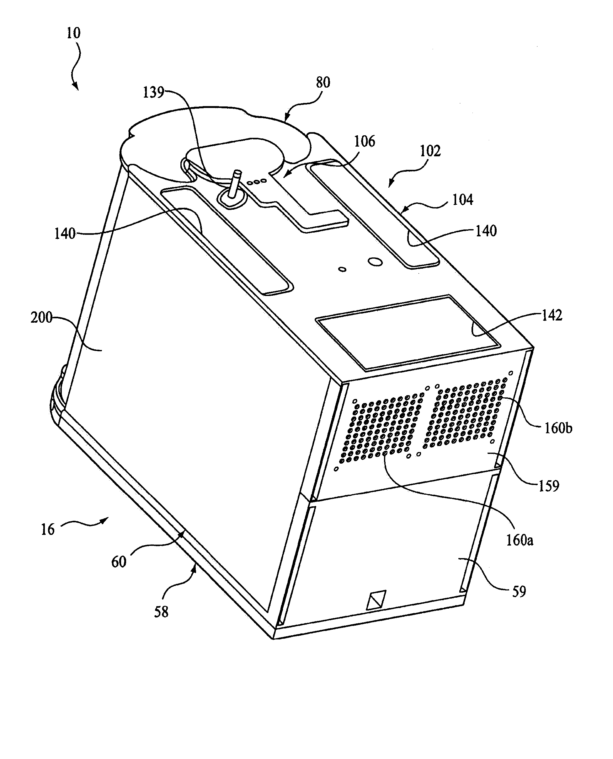
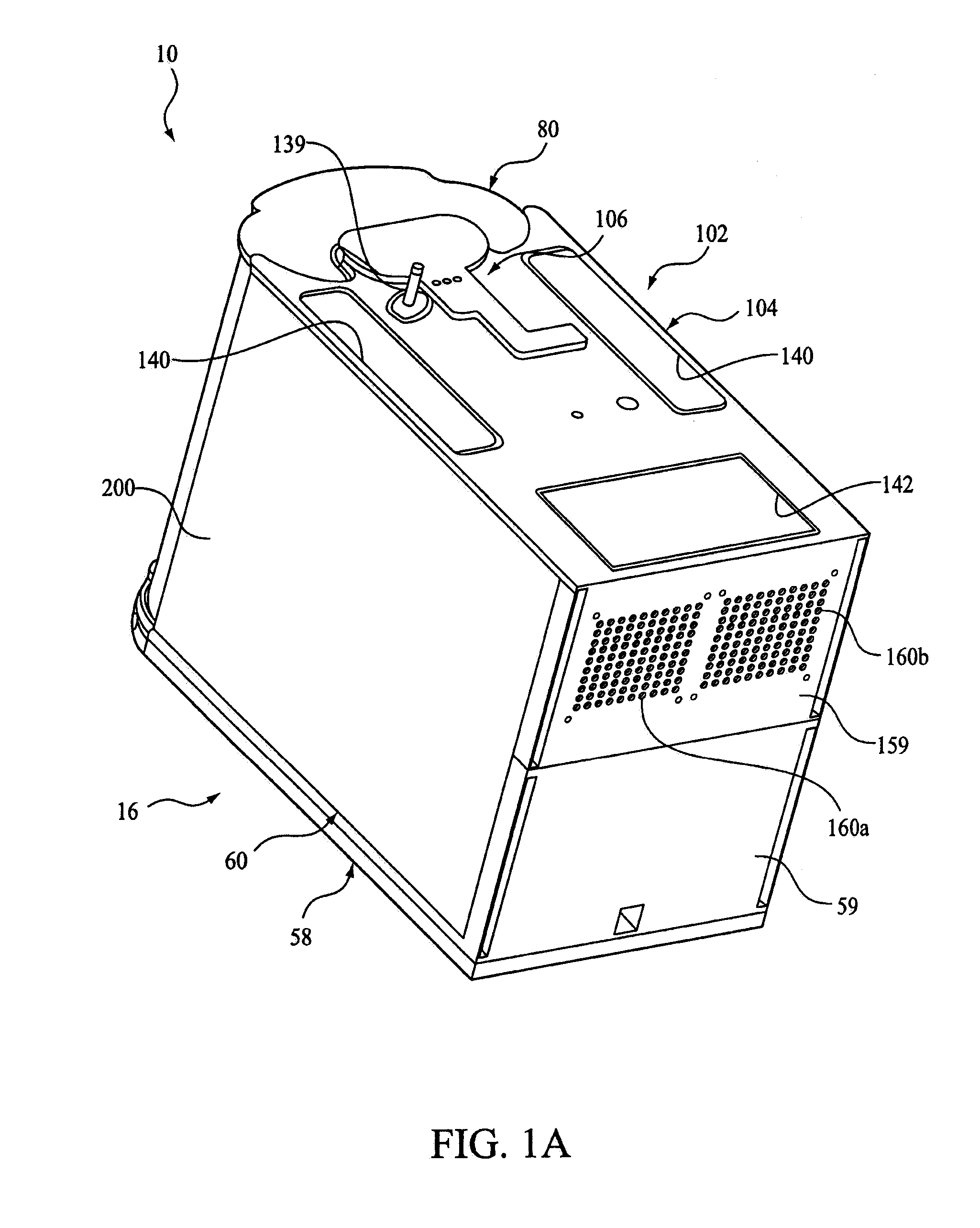
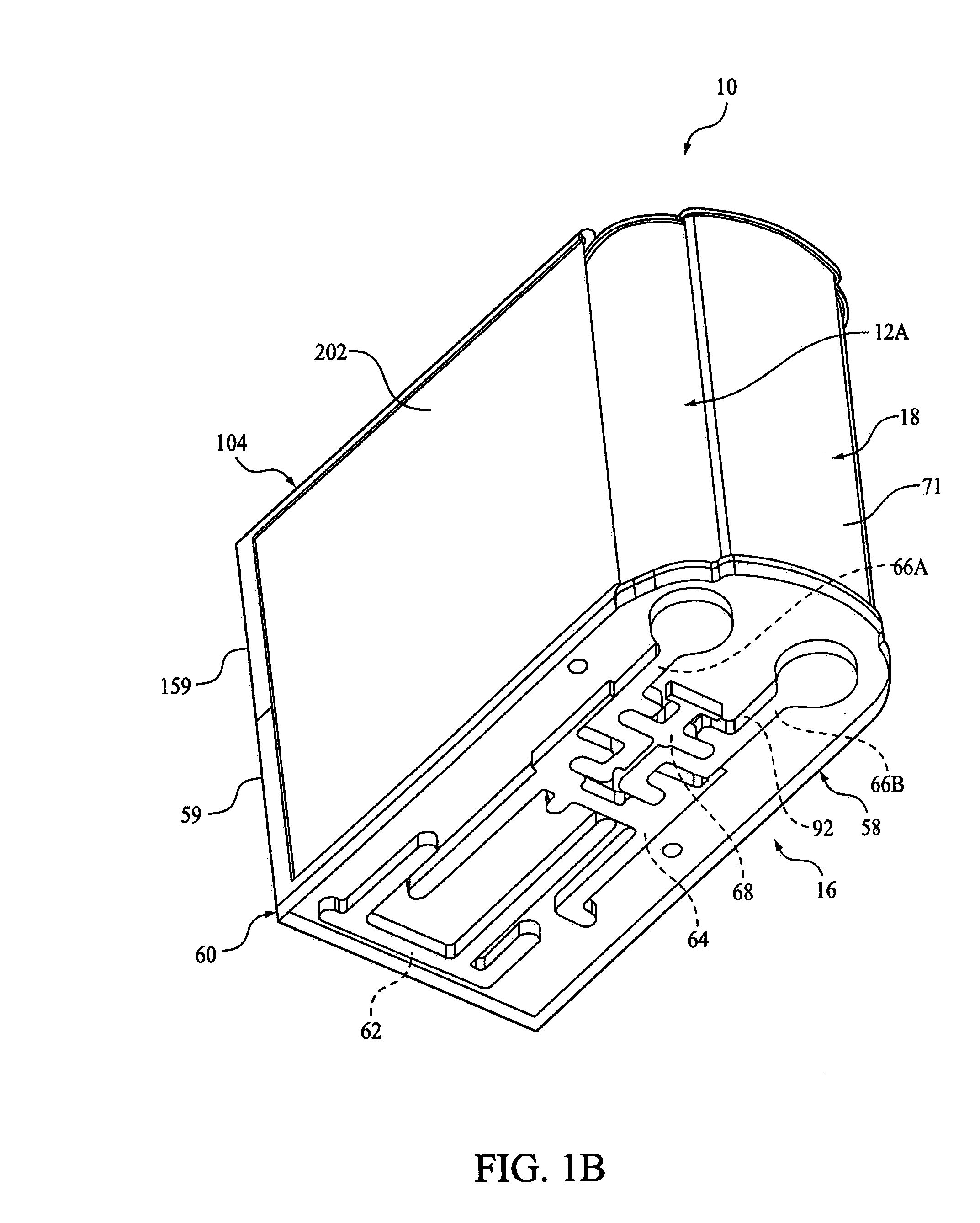
[0049]FIGS. 1A-3 illustrate a portable oxygen concentrator apparatus 10 according to the principles of the present invention. Generally, apparatus 10 includes a plurality of sieve beds or tanks 12A, 12B, a compressor 14, a lower or air manifold 16 defining a plurality of passages 62-68 therein, a storage tank or reservoir 18, a set of air control valves 20 for creating one or more flow paths through the passages 62-68 within the air manifold 16, and an upper or oxygen delivery manifold 102. A controller 22 is coupled to the air control valves 20 to selectively open and close the air control valves to control airflow through the air manifold 16, and, consequently, through the sieve beds 12. Controller 22 is also coupled to an input / output device 23 that is used, for example, to set the operating parameters, such as the oxygen flow rate, of the apparatus.

[0050] It should be noted that the air control valves are collectively referred to using reference number 20, and are individually ...


PUM

PropertyMeasurementUnit
Pressureaaaaaaaaaa
Massaaaaaaaaaa
Volumeaaaaaaaaaa

Abstract

A compressor suitable for use in a portable oxygen concentrator. In one exemplary embodiment, the compressor includes a crankshaft rotatable about a central axis and a plurality of diaphragm assemblies spaced apart around the central axis generally within a plane. The diaphragm assemblies include diaphragms movably mounted to respective housings to at least partially define chambers. A plurality of rods extend between respective diaphragms and the crankshaft. The rods are coupled to the crankshaft such that the rods are offset axially from one another along the central axis and are coupled to the diaphragms for cyclically increasing and decreasing pressure within the chambers as the crankshaft rotates about the central axis.

Description

CROSS-REFERENCE TO RELATED APPLICATIONS [0001] This application claims priority under 35 U.S.C. § 119(e) from provisional U.S. patent application Nos. 60 / 788,916, filed Apr. 3, 2006; 60 / 744,164, filed Apr. 3, 2006; 60 / 744,197 filed Apr. 3, 2006; 60 / 744,271, filed Apr. 4, 2006; and 60 / 744,272, filed Apr. 4, 2006, the contents of each of which are incorporated herein by reference.1. FIELD OF THE INVENTION [0002] The present invention relates generally to compressors, to portable oxygen concentrators including compressors, and methods for making and using compressors, e.g., to compress air drawn into oxygen concentrators, and to methods for making and using oxygen concentrators. 2. DESCRIPTION OF THE RELATED ART [0003] Lung diseased patients often need supplemental oxygen to improve their comfort and / or quality of life. Stationary sources of oxygen are available, e.g., oxygen lines in hospitals or other facilities, that may provide oxygen to patients. To allow some mobility, cylinders ...

Claims


Application Information

Patent Timeline
IPC IPC(8): B01D53/02F01B1/06F04B1/04
CPCA61M16/10B01D2259/455B01D2259/4533B01D2257/102B01D2256/12F04B43/021B01D53/047B01D53/0454B01D53/0446B01D53/0407B01D2253/108F04B43/02A61M16/101A61M16/107A61M2016/1025A61M2202/0208A61M2202/03A61M16/0051A61M16/026A61M2202/0007
Inventor BLISS, PETER L.ATLAS, CHARLES R.HALPERIN, SCOTT C.
Owner RESPIRONICS OXYTEC
Learn More