Broadband impedance matching circuit using high pass and low pass filter sections

a filter section and high-pass filter technology, applied in the field of impedance matching, can solve the problems of narrow-banded pi and t networks, inapplicability to broadband impedance matching, and increase the reflection of return loss, so as to improve the return loss, increase bandwidth, and broader band match

Inactive Publication Date: 2008-02-21
HARRIS CORP
View PDF7 Cites 13 Cited by
  • Summary
  • Abstract
  • Description
  • Claims
  • Application Information

AI Technical Summary

Benefits of technology

[0016]More particularly, a high pass filter section followed by a low pass filter section yield considerably broader band matching than two high pass sections or two low pass filter sections. Moreover, by alternating the high pass filter sections with the low pass filter sections, significantly fewer elements are required for a given result than non-alternating prior art cascaded filter sections. Consequently, the alternating filter sections according to the present invention significantly improves the return loss at increased bandwidths.

Problems solved by technology

Unfortunately, however, Pi and T networks are narrow-banded and therefore not suitable for broadband impedance matching.
Unfortunately, the aforementioned prior art impedance matching circuits are complex in design and require many elements that appreciably increases the return loss reflection.

Method used


Image

  • Broadband impedance matching circuit using high pass and low pass filter sections
  • Broadband impedance matching circuit using high pass and low pass filter sections
  • Broadband impedance matching circuit using high pass and low pass filter sections

Examples


Embodiment Construction

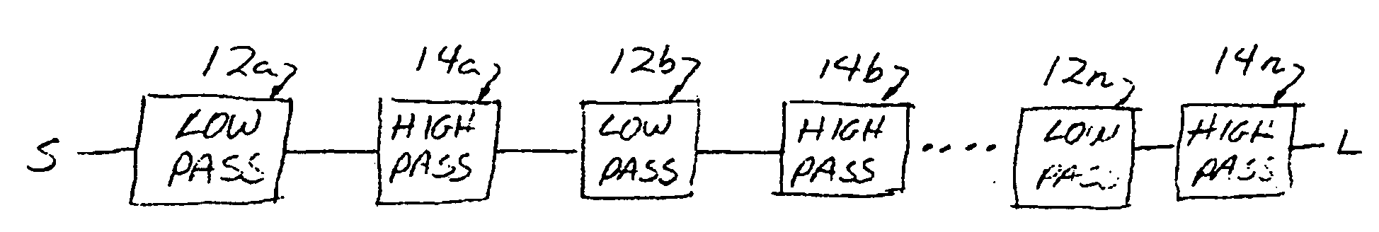
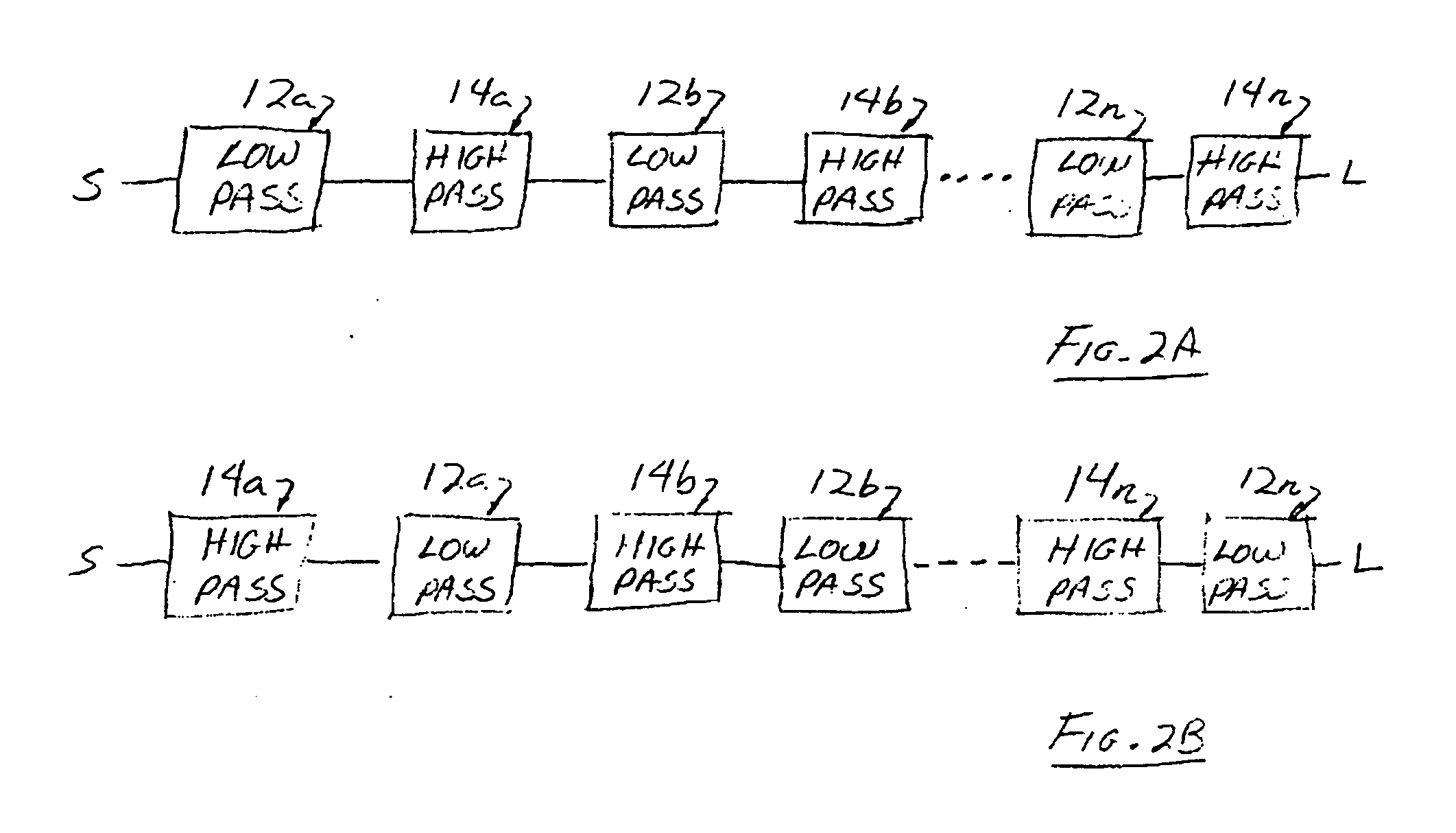
[0022]Referring to FIG. 2, the preferred embodiment of the broadband impedance matching circuit 10 comprises a plurality of low pass filters 12 and a plurality of high pass filters 14 alternatingly cascaded together between a source S whose impedance is to be matched to the impedance of a load L. The alternating cascaded sequence may begin or end with a low pass filter or a high pass filter (FIG. 2A shows the sequence beginning with a low pass section followed by a high pass section whereas FIG. 2B shows the sequence beginning with a high pass section followed by a low pass section).

[0023]More particularly, in FIG. 2A the output of the first low pass filter 12a is connected to the input of the first high pass filter 12b. Then, the output of the first high pass filter 12a is connected to the input of the second low pass filter 12b whose output is connected to the input of the second high pass filter 14b. Likewise, the output of the second high pass filter 14b is connected to the inpu...


PUM


Abstract

A broadband impedance matching circuit using high pass and low pass filter sections alternatingly cascaded together to yield considerably broader band matching than two high pass sections or two low pass filter sections. By alternating the high pass filter sections with the low pass filter sections, significantly fewer elements are required for a given result than non-alternating prior art cascaded filter sections. Consequently, the alternating filter sections according to the present invention significantly improves the return loss at increased bandwidths.

Description

STATEMENT REGARDING FEDERALLY SPONSORED RESEARCH OR DEVELOPMENT[0001]The United States Government has certain rights in and to this invention pursuant to Government Contract No. FA8709-04C-0010.BACKGROUND OF THE INVENTION[0002]1. Field of the Invention[0003]This invention relates to impedance matching. More particularly, this invention relates to broadband impedance matching employing high pass and low pass filters.[0004]2. Description of the Background Art[0005]The maximum transfer of power from a source to its load occurs when the load impedance is equal to the complex conjugate of the source impedance. More specifically, when the load impedance is equal to the complex conjugate of the source impedance, any source reactance is resonated with an equal but opposite load reactance, leaving only equal resistive values for the source and load impedances. Maximum power is thus transferred from the source to the load because the source resistance equals the load resistance.[0006]The simp...

Claims


Application Information

Patent Timeline
Patent Type & Authority Applications(United States)
IPC IPC(8): H03H7/38
CPCH03F1/56H03H11/28H03H7/38H03F2200/387
Inventor TALBOT, ROBERT D.
Owner HARRIS CORP
Why Eureka
Try Eureka