
Bollard assembly

a technology of boltards and bollards, applied in the direction of gearing, instruments, ways, etc., can solve the problems of loss of hydraulic fluid pressure, disadvantaged bollards supported by gaseous pressure, and sometimes exhibited volume loss

Active Publication Date: 2008-02-14
NEENAH FOUNDRY
View PDF13 Cites 23 Cited by
  • Summary
  • Abstract
  • Description
  • Claims
  • Application Information

AI Technical Summary

Benefits of technology

"The present invention relates to a bollard assembly that is designed to protect buildings or structures from vehicular traffic. The bollard assembly is retractable and can be raised and lowered for vehicle access. It is made up of several components, including a base flange, a bollard housing, and a shaft assembly. The bollard assembly is designed to be mounted in ground with minimal soil conditions. The technical effects of the invention include improved protection against vehicular traffic, reduced loss of hydraulic fluid pressure, and improved durability over extended periods of time. The bollard assembly is also designed to be easily maintained and operated."

Problems solved by technology

Hydraulic bollards are disadvantaged by seals that sometimes deteriorate and result in a loss of hydraulic fluid pressure.
On the other hand, bollards supported by gaseous pressure are disadvantaged by the loss of volume sometimes exhibited as ambient temperatures decrease.

Method used


Image

  • Bollard assembly
  • Bollard assembly
  • Bollard assembly

Examples


Embodiment Construction

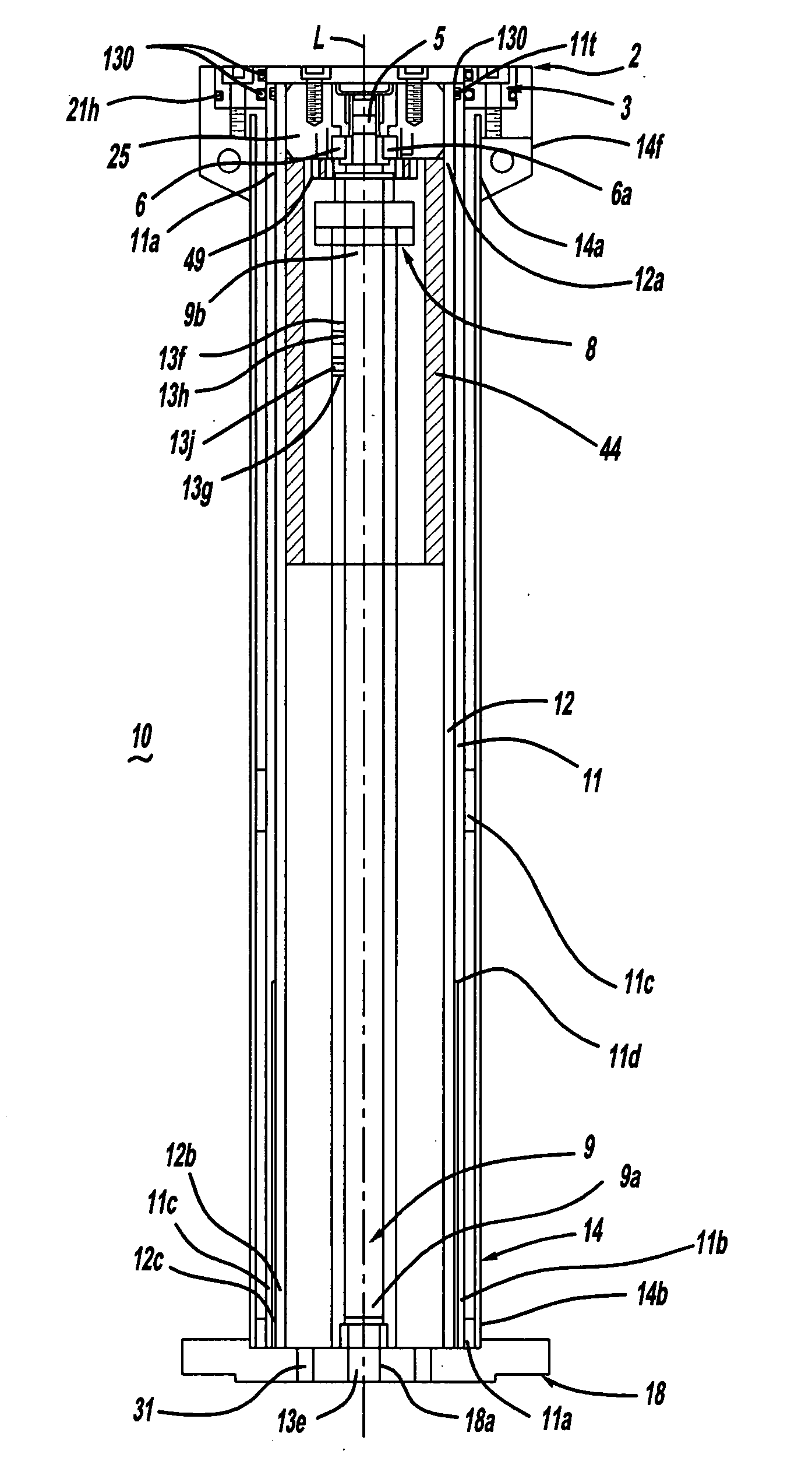
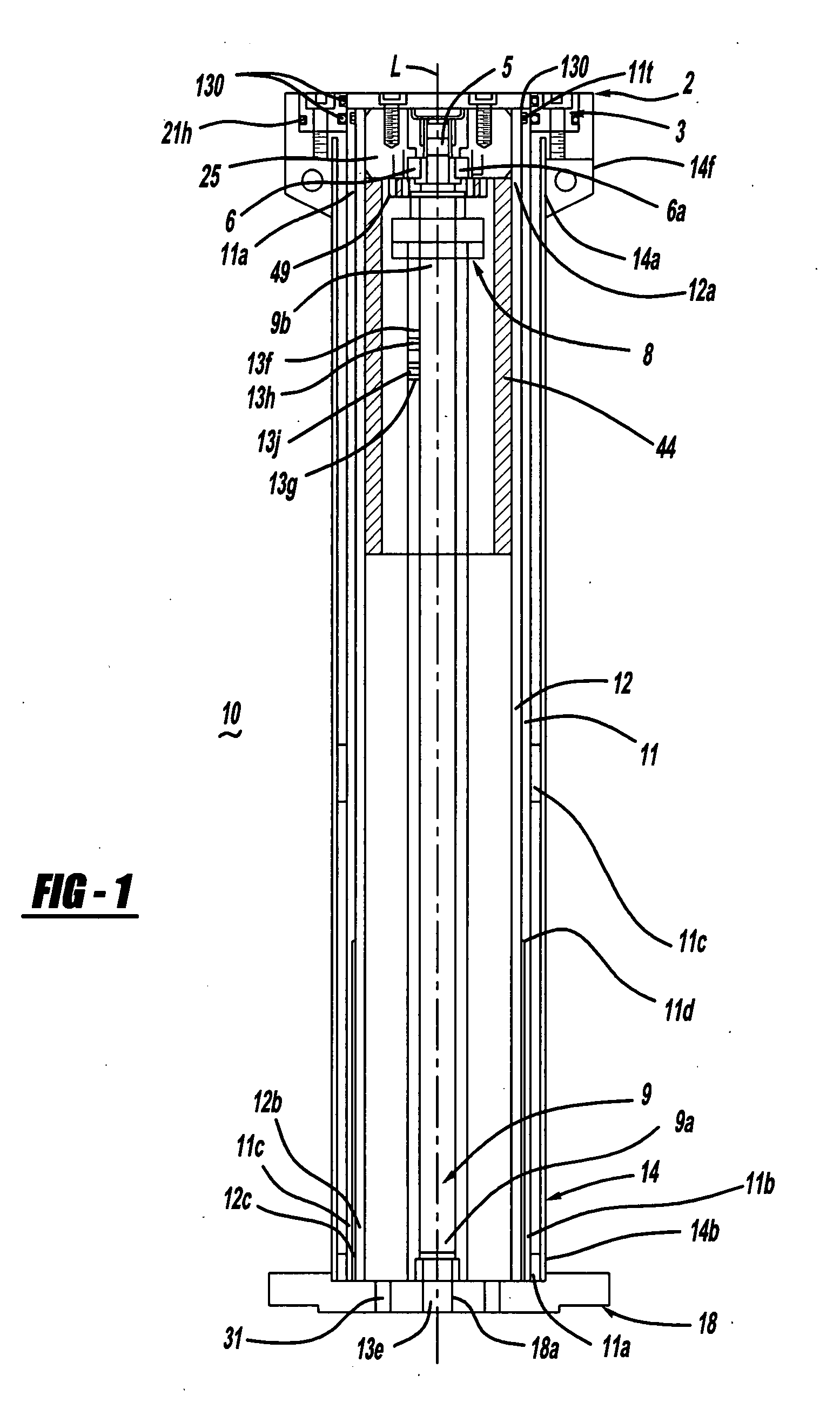
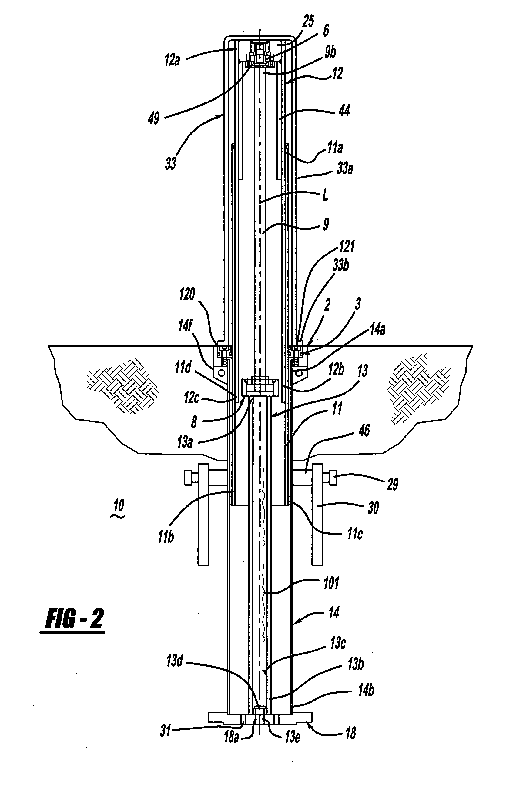
[0018]FIGS. 1 and 2 show cross-sectional views of a bollard assembly 10 in accordance with one embodiment of the present invention. As seen in FIGS. 1 and 2, bollard assembly 10 includes is retractable and operable on a screw drive shaft 9. Bollard assembly 10 also includes a base flange 18 and a bollard housing 14 secured to the base flange for mounting of the other bollard assembly components therein. Most components of the bollard assembly may be nitride coated using known processes for maximum corrosion protection and wear resistance. After nitride coating of a component, an auto ferritic may be applied by any suitable vendor (for example, Henkels & McCoy of Blue Bell, Pa.) to enhance corrosion resistance.

[0019] Housing 14 has a first end 14a and a second end 14b. Housing 14 is formed from steel plate which is rolled into a cylinder having a longitudinal axis L, and welded along a seam. The basic steel tube from which housing 14 is formed can be fabricated by any suitable vendo...


PUM


Abstract

A telescoping bollard assembly is provided. The bollard assembly includes a threaded shaft and a shaft housing structure containing a lubricant source in fluid communication with the shaft threads. A lubricant is positioned in the lubricant source in contact with the threaded portion of the shaft. A funnel portion is in fluid communication with the lubricant source, and a shaft guide portion is in fluid communication with the funnel portion. A portion of the shaft projects to an exterior of the housing through a shaft exit portion. The shaft exit portion is in fluid communication with the shaft guide portion and defines a flow path for the lubricant to the lubricant source. Rotation of the shaft urges lubricant from the lubricant source sequentially into the funnel portion, the shaft guide portion, and the shaft exit portion, whereby the lubricant is returned to the lubricant source.

Description

CROSS-REFERENCE TO RELATED APPLICATIONS [0001] The present application claims the benefit of U.S. Provisional Application Ser. No. 60 / 832,781, filed on Jul. 24, 2006.BACKGROUND OF THE INVENTION [0002] A bollard is typically employed to prevent vehicular traffic inward or past the point of the bollard. Accordingly, any building or structure that requires protection may be protected by a plurality of bollards deployed about the periphery thereof. From a design standpoint, bollards must be strong enough to prevent and / or substantially slow movement of a vehicle between the bollard and the structure to be protected. Furthermore, periodically, vehicular access is desired and therefore the bollards must be designed in retractable fashion, thereby permitting vehicular travel over the recessed bollard. [0003] Several retractable bollard designs are known and employ various deployment methods including hydraulic or pressurized gas means. Hydraulic bollards are disadvantaged by seals that som...

Claims


Application Information

Patent Timeline
Patent Type & Authority Applications(United States)
IPC IPC(8): E01F13/04E01F15/00F16C3/03F16K15/00
CPCY10T74/22E01F13/046
Inventor STADLER
Owner NEENAH FOUNDRY
Learn More