LCD with source driver and data transmitting method thereof
- Summary
- Abstract
- Description
- Claims
- Application Information
AI Technical Summary
Benefits of technology
Problems solved by technology
Method used
Image
Examples
first embodiment
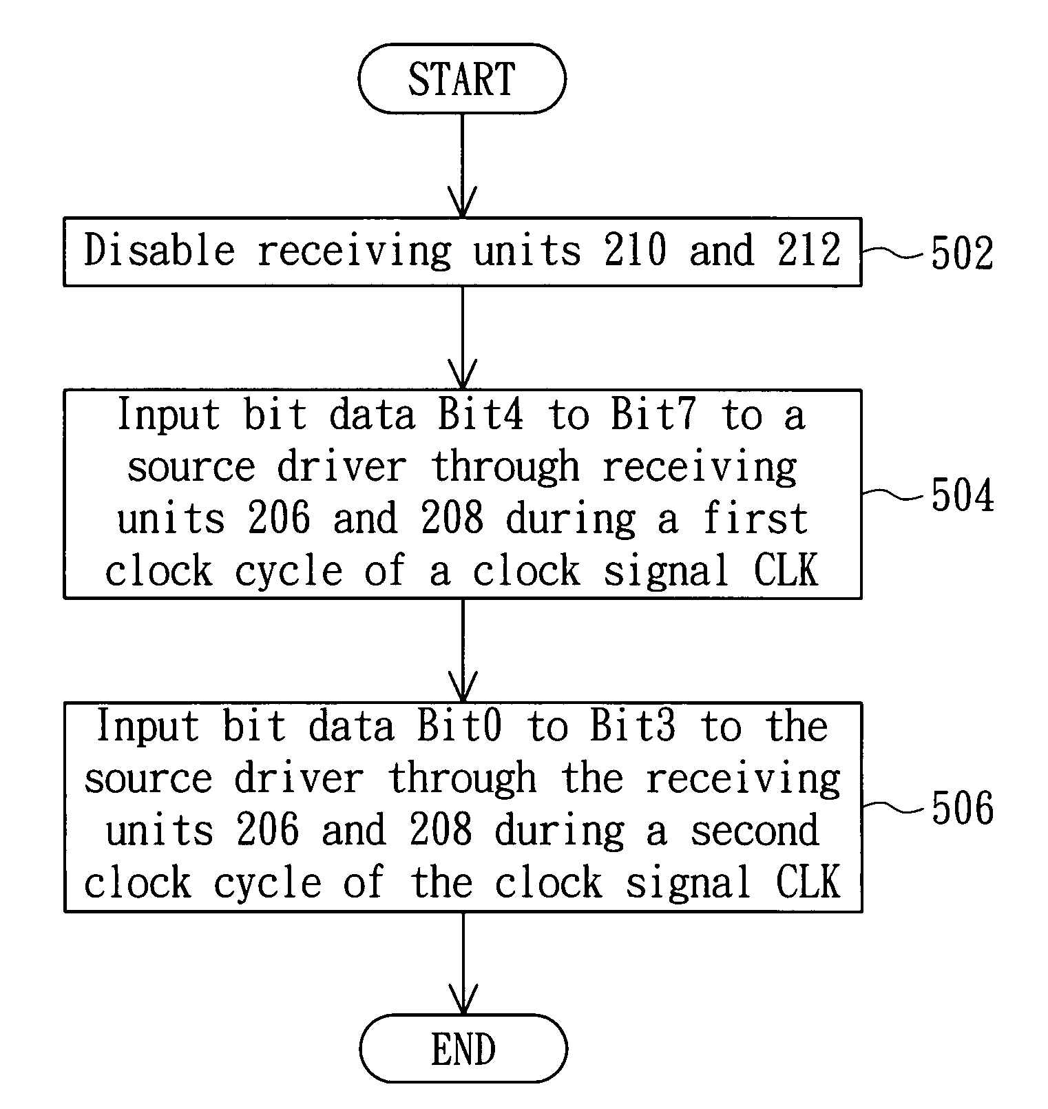
[0025]FIG. 3A shows a circuit layout of the timing controller 202 and the source driver 204 when the source driver 204 operates in the first mapping operation mode. As shown in FIG. 3A, when the source driver 204 operates in the first mapping mode, the receiving units 210 and 212 and the transmission paths 204b3 and 204b4 are disabled (the disabled receiving units 210 and 212 and the disabled transmission paths 204b3 and 204b4 are represented by dashed lines), and the transmission paths 204b1 and 204b2 are enabled. Thus, the timing controller 202 only can output the red sub-pixel data to the receiving units 206 and 208 through the buses 2051 to 2054, and the registers 214 and 216 are respectively coupled to the registers 218 and 220 in series.
[0026]FIG. 3B shows timing charts of the bit data on the buses 2051 to 2054 when the source driver 204 operates in the first mapping operation mode.
[0027]At a rising edge of a first clock cycle of the clock signal CLK, the timing controller 202...
second embodiment
[0043]FIG. 6A shows a circuit layout of the timing controller 202 and the source driver 204 when the source driver 204 operates in the second mapping operation mode. As shown in FIG. 6A, the source driver 204 operating in the second mapping operation mode differs from the source driver 204 operating in the first mapping operation mode because the disabled receiving units and data transmission paths are different from each other. Meanwhile, the bit data Bit0 to Bit7 outputted from the timing controller 202 are received through different buses. When the source driver 204 operates in the second mapping operation mode, the receiving units 206 and 208 and the transmission paths 204b1 and 204b2 are disabled (the disabled receiving units 206 and 208 and the disabled transmission paths 204b3 and 204b4 are represented by dashed lines). In addition, the transmission paths 204b3 and 204b4 are enabled.
[0044]FIG. 6B shows timing charts of the bit data on the buses 2055 to 2058 when the source dr...
PUM
 Abstract
Description
Claims
Application Information
 - R&D
- Intellectual Property
- Life Sciences
- Materials
- Tech Scout
- Unparalleled Data Quality
- Higher Quality Content
- 60% Fewer Hallucinations
Browse by: Latest US Patents, China's latest patents, Technical Efficacy Thesaurus, Application Domain, Technology Topic, Popular Technical Reports.
© 2025 PatSnap. All rights reserved.Legal|Privacy policy|Modern Slavery Act Transparency Statement|Sitemap|About US| Contact US: help@patsnap.com


