Eureka AIR delivers breakthrough ideas for toughest innovation challenges, trusted by R&D personnel around the world.

Cleveland round tip (CRT) needle

a needle and round tip technology, applied in the direction of guide needles, intravenous devices, catheters, etc., can solve the problems of ineffective treatment, easy damage or penetration of sharp needles, use of sharp cutting points or edges, etc., to facilitate the penetration of cannulas, facilitate the delivery of medication, and mitigate penetration injury

Inactive Publication Date: 2008-01-31
GRABINSKY ANDREAS
View PDF12 Cites 123 Cited by
  • Summary
  • Abstract
  • Description
  • Claims
  • Application Information

AI Technical Summary

Benefits of technology

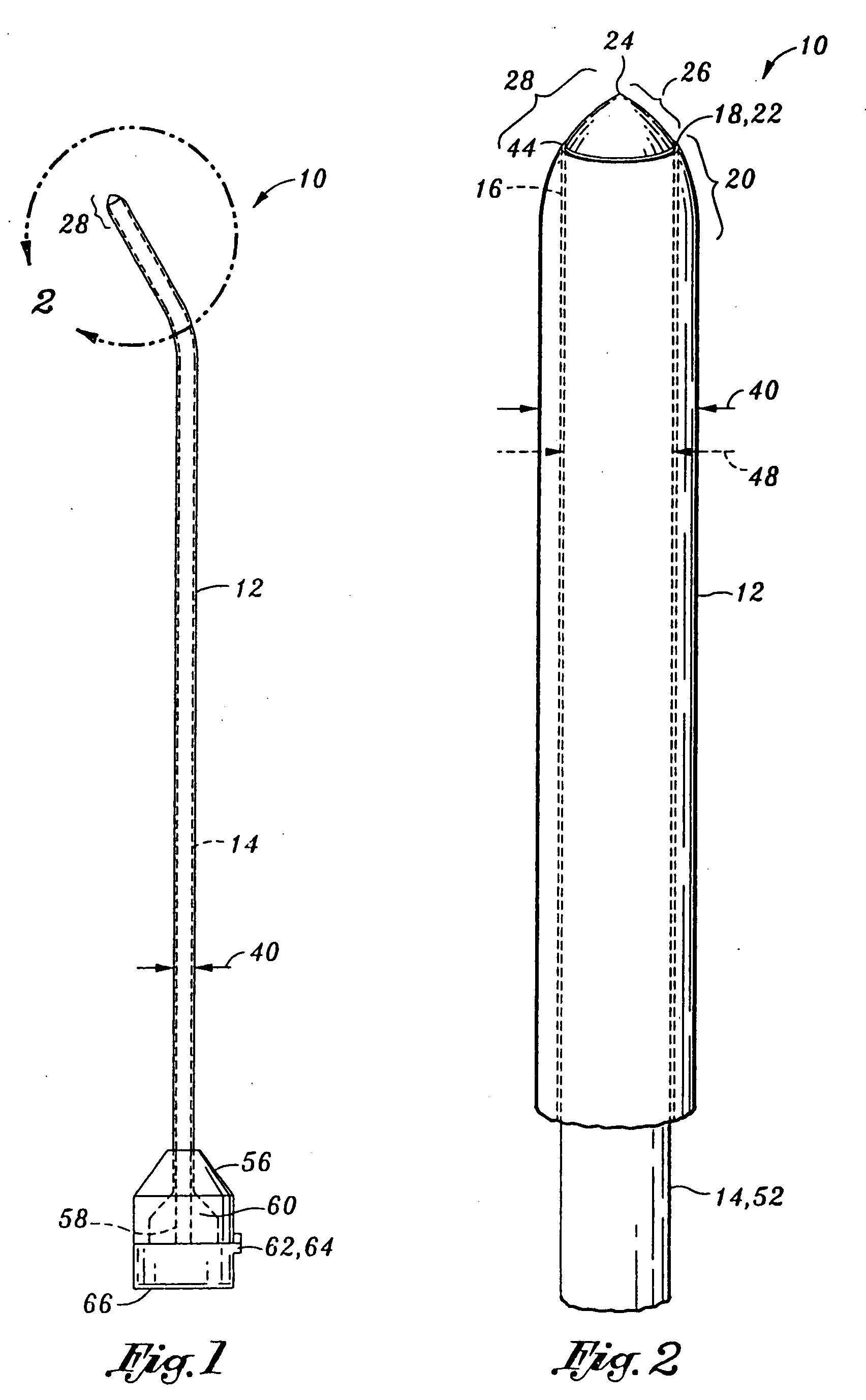
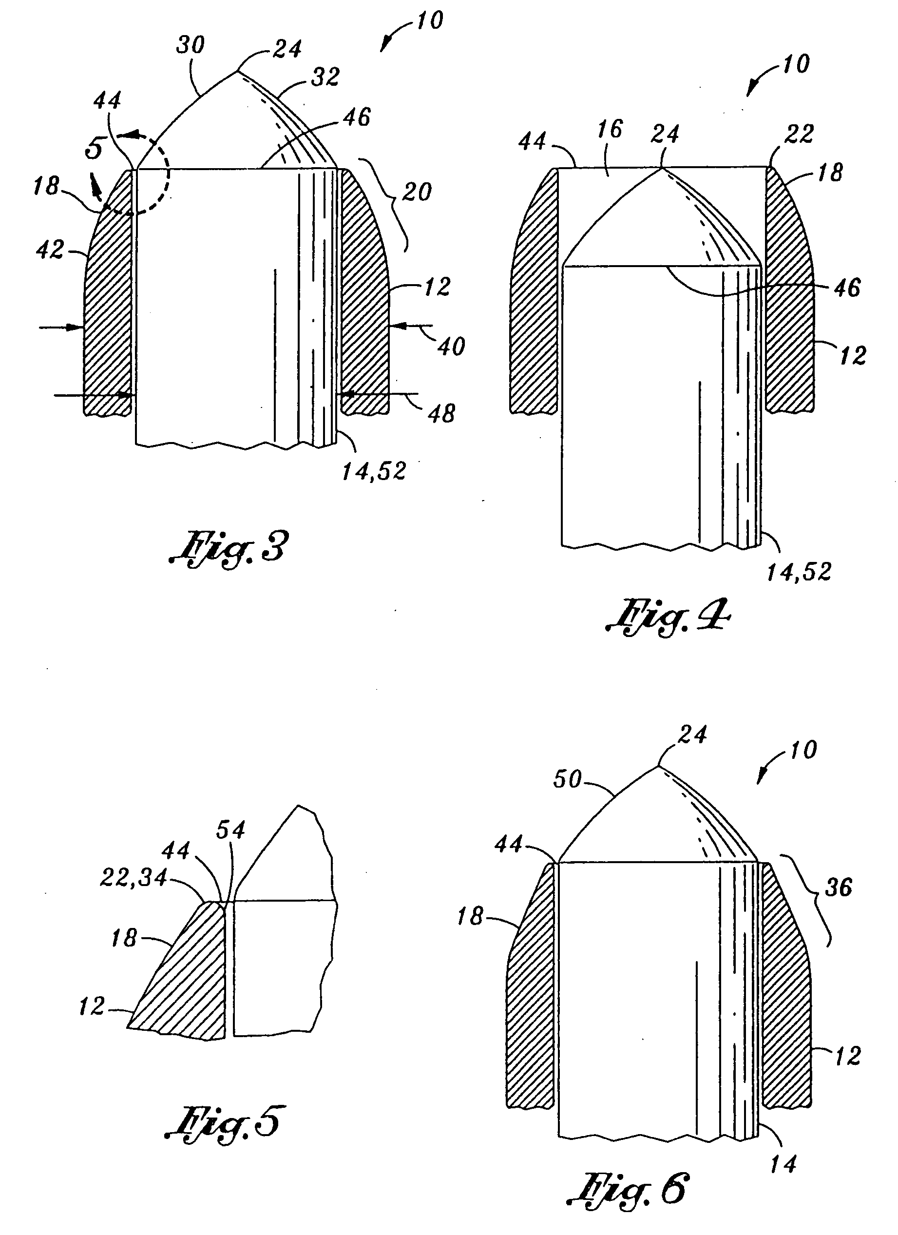
[0011] In accordance with an embodiment of the present invention, a needle assembly is provided for mitigating penetration injury during an injection into a desired area. Such injection may be in regard to a peripheral nerve block, sympathetic nerve block, or a transforaminal injection, or other types of injections. The assembly comprises a cannula and a stylet. The cannula includes an axially-disposed passageway and a cannula rim disposed at a distal end thereof. The cannula rim defines a non-cutting edge. The stylet is tapered to a stylet tip at a leading end thereof. The stylet is removably positionable within the passageway of the cannula with the stylet tip being longitudinally extendable beyond the cannula rim. The leading end and the cannula rim collectively form a piercing head. In use, the piercing head facilitates penetration of the cannula into the desired area. Subsequent to penetration into the desired area, the stylet tip may be retracted from beyond the cannula rim. This retraction facilitates delivery of the medication through the passageway and exposes the non-cutting edge of the cannula rim. Thus, the exposed non-cutting cannula rim may mitigate further penetration of the needle assembly.
[0013] In accordance with another embodiment of the present invention, a needle assembly is provided for mitigating penetration injury during an injection of medication into a desired area. The assembly comprises a cannula and a stylet. The cannula includes an axially-disposed passageway and defines a cannula diameter, a cannula collar, and a distal edge. The cannula diameter decreases from the cannula collar until reaching the distal edge to form a cannula rim. The cannula rim defines a non-cutting edge. The stylet defines a leading end, a stylet collar, and a stylet tip. The stylet tapers to the stylet tip at the leading end. The stylet is removably positionable within the passageway with the stylet collar being approximately adjacent the cannula rim to facilitate penetration of the cannula into the desired area. In use, the stylet tip may be retracted from beyond the cannula rim subsequent to penetration into the desired area to facilitate delivery of the medication through the passageway and to expose the non-cutting edge of the cannula rim to mitigate further penetration.
[0014] The leading end of the stylet may define an axially convex surface which tapers until converging to form the stylet tip. Additionally, the stylet may further define a stylet diameter, and the stylet diameter may increasingly decrease from the stylet collar until reaching the stylet tip. The stylet tip may be axially aligned with the cannula. The stylet may define a distal surface having a continuous curvature therealong. Further, the stylet may include a substantially cylindrical stylet body. The cannula diameter may increasingly decrease from the cannula collar until reaching the distal edge. Finally, the cannula rim may further define a rounded inner edge.
[0015] In accordance with yet another embodiment of the present invention, a needle assembly is provided for injection of medication into a desired area. The assembly comprises a cannula, a stylet, and a hub. The cannula defines- distal and proximal ends and includes an axially-disposed passageway and a cannula rim disposed at the distal end. The cannula rim defines a non-cutting edge. The stylet is tapered to a stylet tip at the leading end thereof. The stylet is positionable within the passageway with the stylet tip being longitudinally extendable beyond the cannula rim. The leading end and the cannula rim collectively forming a piercing head. The hub is attachable to the proximal end of the cannula and includes a bore. The stylet is insertable into the passageway through the bore, and the hub is operative to longitudinally secure the stylet within the passageway upon formation of the piercing head. In use, the piercing head facilitates penetration of the cannula into the desired area. Subsequent to penetration into the desired area, the stylet tip may be retracted from beyond the cannula rim. This retraction facilitates delivery of the medication through the passageway and exposes the non-cutting edge of the cannula rim to mitigate further penetration.

Problems solved by technology

On the side of the spine and within the muscles are nerves and vessels located, which cannot be seen on fluoroscopy and can therefore easily damaged or penetrated by sharp, cutting needles.
Unfortunately, these prior art needles have certain disadvantageous characteristics that may lead to complications and / or ineffective treatment results.
A first disadvantage of prior art needles lays the use of sharp cutting points or edges.
Although this feature may allow the needle to easily penetrate and reach the desired area, control of the needle is extremely critical because of their sharp points and edges.
Although sharp cutting points and edges may be helpful in facilitating penetration of the needle, they also increase the potential risk of undesired penetration and injury to nerves and surrounding structures.
For example, a sharp needle may cause nerve injuries or penetrate into the intestine or blood vessels, which may result in complications during the procedure.
The adverse outcomes of this regional anesthesia may include temporary nerve injury, paralysis, or death.
However, these needles also have a certain disadvantage in their design: the medication is delivered to the desired area via a side hole.
The delivery mechanism (the side hole) may be imprecise in delivering medication to the desired area, which can be problematic and ineffective for small areas.
Thus, although the tip of the needle may reach the target area without penetrating other structures, the delivery of medication may be ineffectual because the side hole may not be precisely positioned within the desired area.
In such a case, the medication may not be delivered to the nerve root within the desired area.
Another disadvantage associated with these needles is that the tip may be too blunt, making penetration to the desired area more difficult.

Method used


Image

  • Cleveland round tip (CRT) needle
  • Cleveland round tip (CRT) needle
  • Cleveland round tip (CRT) needle

Examples


Embodiment Construction

[0024] Referring now to the drawings wherein the showings are for purposes of illustrating the preferred embodiment invention only and not for purposes of limiting the same, FIG. 1 illustrates a needle assembly 10 for mitigating penetration injury during an injection into a desired area. The embodiments of the present invention described herein may easily penetrate to the desired area, such as a target nerve area adjacent a spinal cord, as may be common in peripheral nerve blocks, sympathetic nerve blocks, and transforaminal injections. As mentioned above, such injections may include those for peripheral nerve blocks, sympathetic nerve blocks, or transforaminal injections, or other types of injections. However, in contrast to prior art needles, embodiment for the present invention are configured to avoid further penetration into the desired area subsequent to the assembly 10 being properly positioned within the desired area, thereby substantially eliminating unintentional penetratio...


PUM


Abstract

A needle assembly is provided for mitigating penetration injury during an injection into a desired area. The assembly comprises a cannula and a stylet. The cannula includes an axially-disposed passageway and a cannula rim disposed at a distal end thereof. The cannula rim defines a non-cutting edge. The stylet is tapered to a stylet tip at a leading end thereof. The stylet is removably positionable within the passageway of the cannula with the stylet tip being longitudinally extendable beyond the cannula rim. The leading end and the cannula rim collectively form a piercing head. The piercing head facilitates penetration of the cannula into the desired area. Subsequent to penetration, retraction of the stylet tip from beyond the cannula rim facilitates delivery of the medication through the passageway and exposes the non-cutting edge of the cannula rim to mitigate further penetration.

Description

CROSS-REFERENCE TO RELATED APPLICATIONS [0001] Not Applicable STATEMENT RE: FEDERALLY SPONSORED RESEARCH / DEVELOPMENT [0002] Not Applicable BACKGROUND [0003] The present invention relates generally to medical needle assemblies, and more particularly to an improved needle assembly featuring a cannula and stylet each having a rounded, non-cutting tip that is specifically adapted to facilitate penetration to a target nerve area without causing nerve injuries and / or penetrating into surrounding structure. [0004] Epidural steroid injection (ESI) is a well known non-surgical treatment designed to alleviate pain in the neck, arm, low back, and leg caused by irritation of spinal nerves. Typically, an ESI produces long-lasting relief for a patient by delivering an anesthetic agent to the irritated and inflamed spinal nerve. During the ESI process, a needle is introduced into epidural space near the spinal cord, in a designated area as close to the irritated nerve as possible. Upon reaching th...

Claims


Application Information

Patent Timeline
Patent Type & Authority Applications(United States)
IPC IPC(8): A61M25/06
CPCA61M25/065A61M25/0606
Inventor GRABINSKY, ANDREAS
Owner GRABINSKY ANDREAS
Why Eureka
Eureka Blog
Learn More