
Electro-mechancial strap stack in robotic arms

Active Publication Date: 2008-01-24
INTUITIVE SURGICAL OPERATIONS INC
View PDF105 Cites 84 Cited by
  • Summary
  • Abstract
  • Description
  • Claims
  • Application Information

AI Technical Summary

Problems solved by technology

Additionally, there is often electrical cabling in a robotic surgical arm that may be subject to bending and chaffing around joints of motion.

Method used


Image

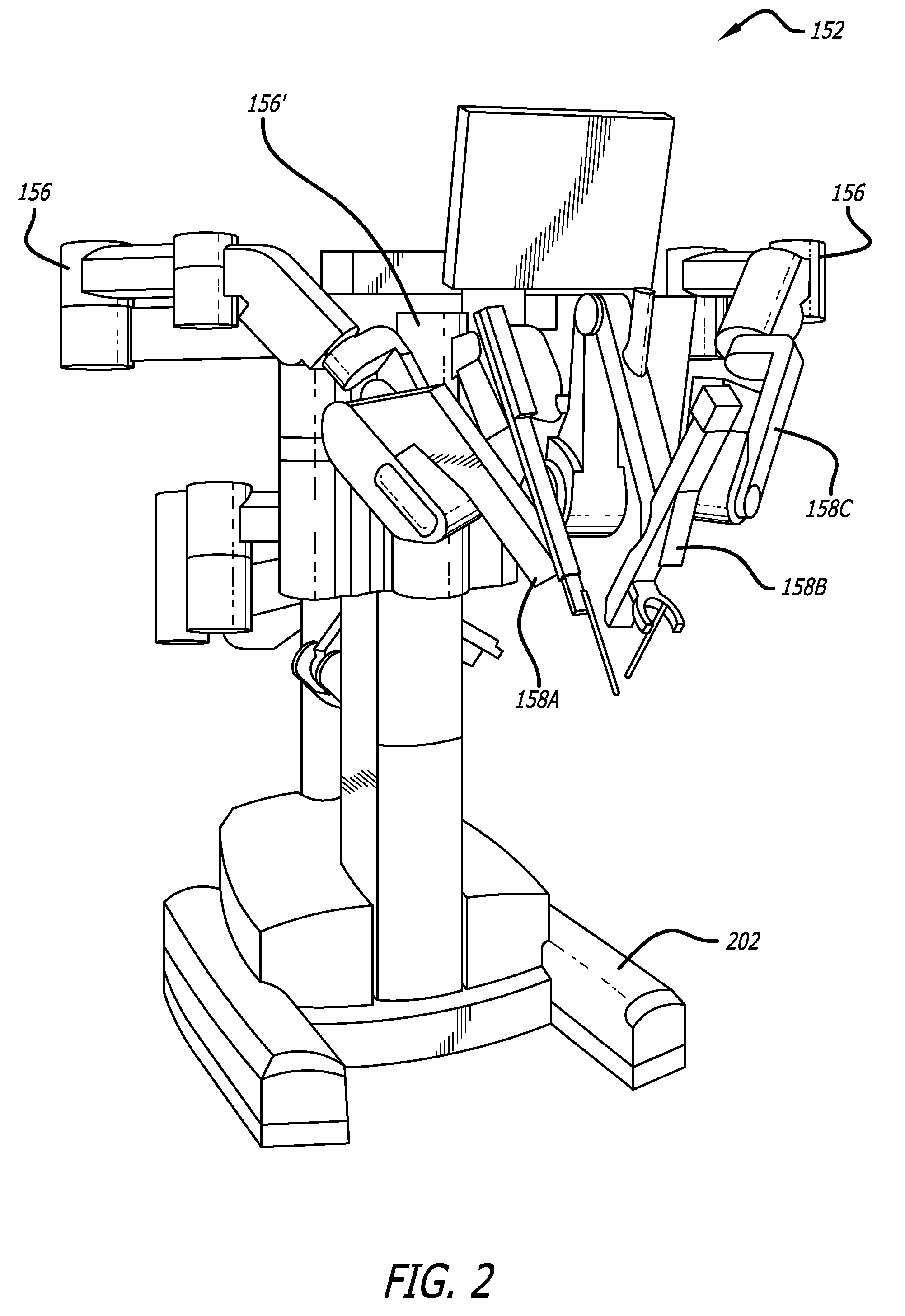
  • Electro-mechancial strap stack in robotic arms
  • Electro-mechancial strap stack in robotic arms
  • Electro-mechancial strap stack in robotic arms

Examples


Embodiment Construction

[0023] In the following detailed description of the embodiments of the invention, numerous specific details are set forth in order to provide a thorough understanding of the embodiments of the invention. However, it will be obvious to one skilled in the art that the embodiments of the invention may be practiced without these specific details. In other instances well known methods, procedures, components, and circuits have not been described in detail so as not to unnecessarily obscure aspects of the embodiments of the invention.

[0024] The embodiments of the invention include a method, apparatus, and system for robotic surgical systems. In one embodiment of the invention a robotic surgical system is provided including flat electrical conductors over pulleys in a strap drive-train of a robotic surgical arm.

[0025] In one embodiment of the invention, a strap drive-train for use in a robotic surgical arm to enable movement of a linkage assembly of the robotic surgical arm is provided. ...


PUM


Abstract

In one embodiment of the invention, a strap drive-train for use in a robotic arm to enable movement of a linkage assembly of the robotic arm is provided. The linkage assembly includes a plurality of links pivotally coupled in series together at a plurality of joints, respectively, for movement of the robotic arm about a pitch axis. The strap drive-train includes a first driver pulley rigidly coupled to a link of the plurality of links and a second driver pulley rigidly coupled to another link of the plurality of links. The electro-mechanical strap stack includes at least one of a ground strap and an electrical cable strap in a stacked configuration with a drive strap, wherein the electro-mechanical strap stack is connected between the first driver pulley and the second driver pulley through a middle link.

Description

CROSS-REFERENCE TO RELATED APPLICATIONS [0001] This non-provisional patent application claims the benefit of U.S. Provisional Patent Application No. 60 / 752,788, entitled “FLAT ELECTRICAL CONDUCTORS OVER PULLEYS IN A STRAP DRIVE-TRAIN OF A ROBOTIC SURGICAL ARM” filed by Todd R. Solomon on Dec. 21, 2005; and is also a continuation in part and claims the benefit of U.S. patent application Ser. No. 10 / 957,077, entitled “Offset Remote Center Manipulator for Robotic Surgery”, filed on Sep. 30, 2004 by Thomas G. Cooper and Todd R. Solomon. [0002] This non-provisional patent application also claims the benefit of and is related to U.S. Patent Application No. 60 / 752,514, entitled MULTI-PLY STRAP DRIVE-TRAIN FOR ROBOTIC SURGICAL ARM filed by Todd R. Solomon and Thomas G. Cooper on Dec. 20, 2005, which is hereby incorporated by reference.FIELD [0003] The embodiments of the invention relate generally to wiring power, ground, and signals through a surgical robotic arm. More particularly, the emb...

Claims


Application Information

Patent Timeline
Patent Type & Authority Applications(United States)
IPC IPC(8): A61B17/00
CPCA61B19/2203A61B19/5212A61B2019/2223A61B2017/00477A61B2019/2246B25J9/1045A61B2019/2242A61B34/30A61B34/37A61B34/71A61B90/361A61B2034/715A61B2034/305
Inventor SOLOMON, TODD R.
Owner INTUITIVE SURGICAL OPERATIONS INC
Learn More