Eureka AIR delivers breakthrough ideas for toughest innovation challenges, trusted by R&D personnel around the world.

Touch detection method and system for a touch sensor

a technology of touch sensor and detection method, which is applied in the field of touch sensors, can solve the problems of system sensitivity to multiple, system may fail to detect an actual touch event, and key sensitivity dri

Inactive Publication Date: 2008-01-24
TYCO ELECTRONICS CANADA
View PDF13 Cites 65 Cited by
  • Summary
  • Abstract
  • Description
  • Claims
  • Application Information

AI Technical Summary

Problems solved by technology

One problem with conventional touch sensing systems is that the systems are sensitive to multiple factors that affect the output signals of the key.
As such, the system may detect a faulty touch or the system may fail to detect an actual touch event.
At least some of these factors that affect the output signals of the key are caused by various problems, such as the thickness or type of dielectric material used for the key, the size or positioning of the keys, the size of the user's finger touching the key, the way that a user touches the key, interference caused by noise, unequal key sensitivities caused by manufacturing or environmental factors, drift in key sensitivity due to environmental factors like temperature or humidity, and touches by non-user objects such as metal objects, water, or animals.
However, these control algorithms add complexity and expense to the overall system.

Method used


Image

  • Touch detection method and system for a touch sensor
  • Touch detection method and system for a touch sensor
  • Touch detection method and system for a touch sensor

Examples


Embodiment Construction

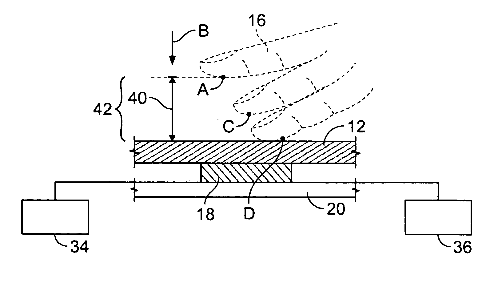
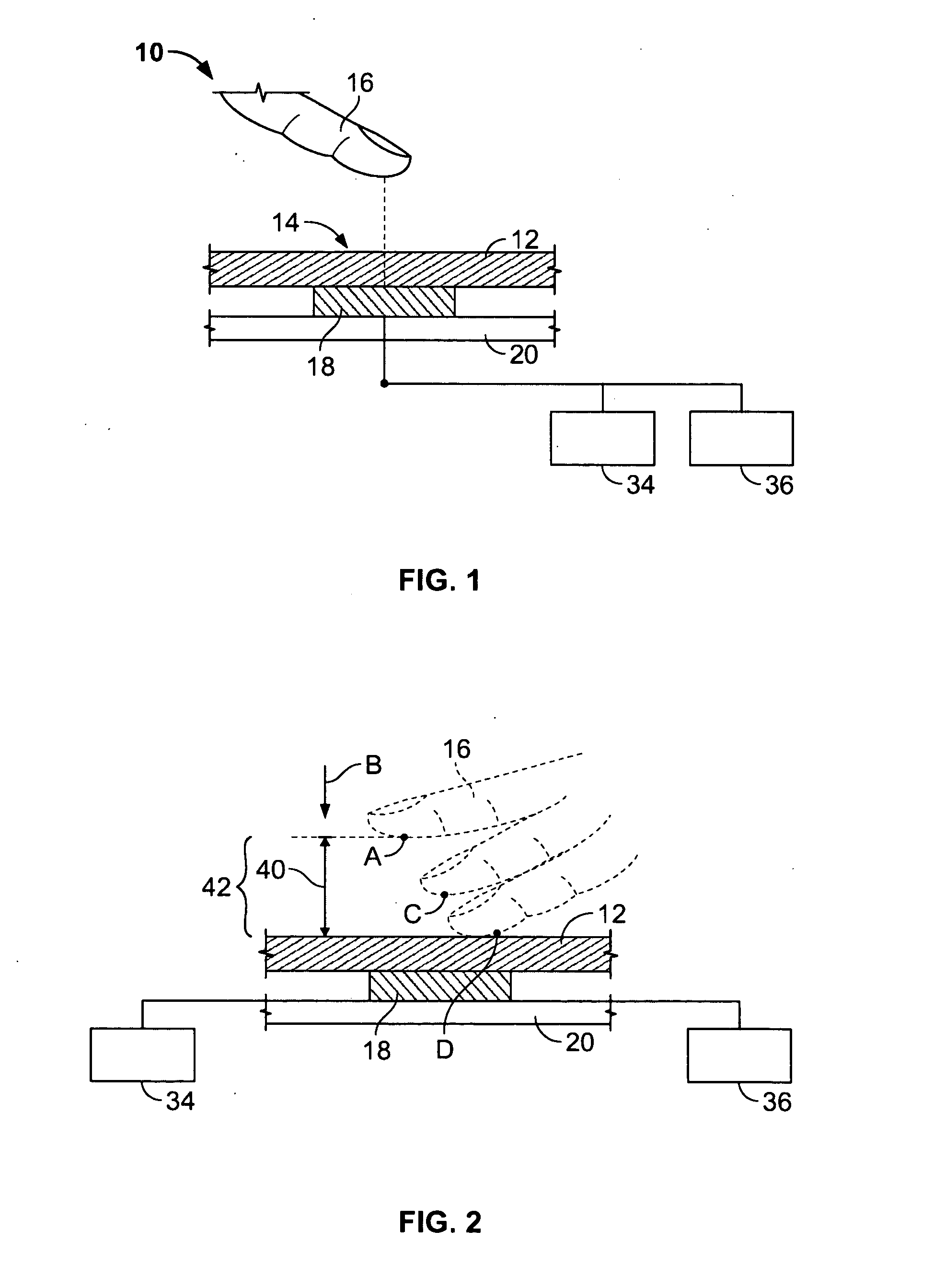
[0014]FIG. 1 is a schematic view of a touch sensor 10. The touch sensor 10 is mounted under a dielectric element 12 and is illustrated in a “touch” condition since a sensing location 14 of the dielectric element 12 is touched by a finger 16 of a user. A touch event occurs when a user physically touches the sensing location 14 or when a user is in close proximity to the sensing location 14, such that the user is interacting with the touch sensor 10. The interaction between the user and the touch sensor 10 is illustrated by the dashed line in FIG. 1. Optionally, the user may be capacitively interacting with the touch sensor 10, wherein the touch sensor 10 detects the capacitive coupling between the user's finger 16 and the touch sensor 10. Alternatively, the user may interact with the touch sensor 10 in other detectable ways, such as by an electromagnetic interaction, an electronic field, a field disturbance, a charge transfer, a radiation transfer, and the like.

[0015]The touch sensor...


PUM


Abstract

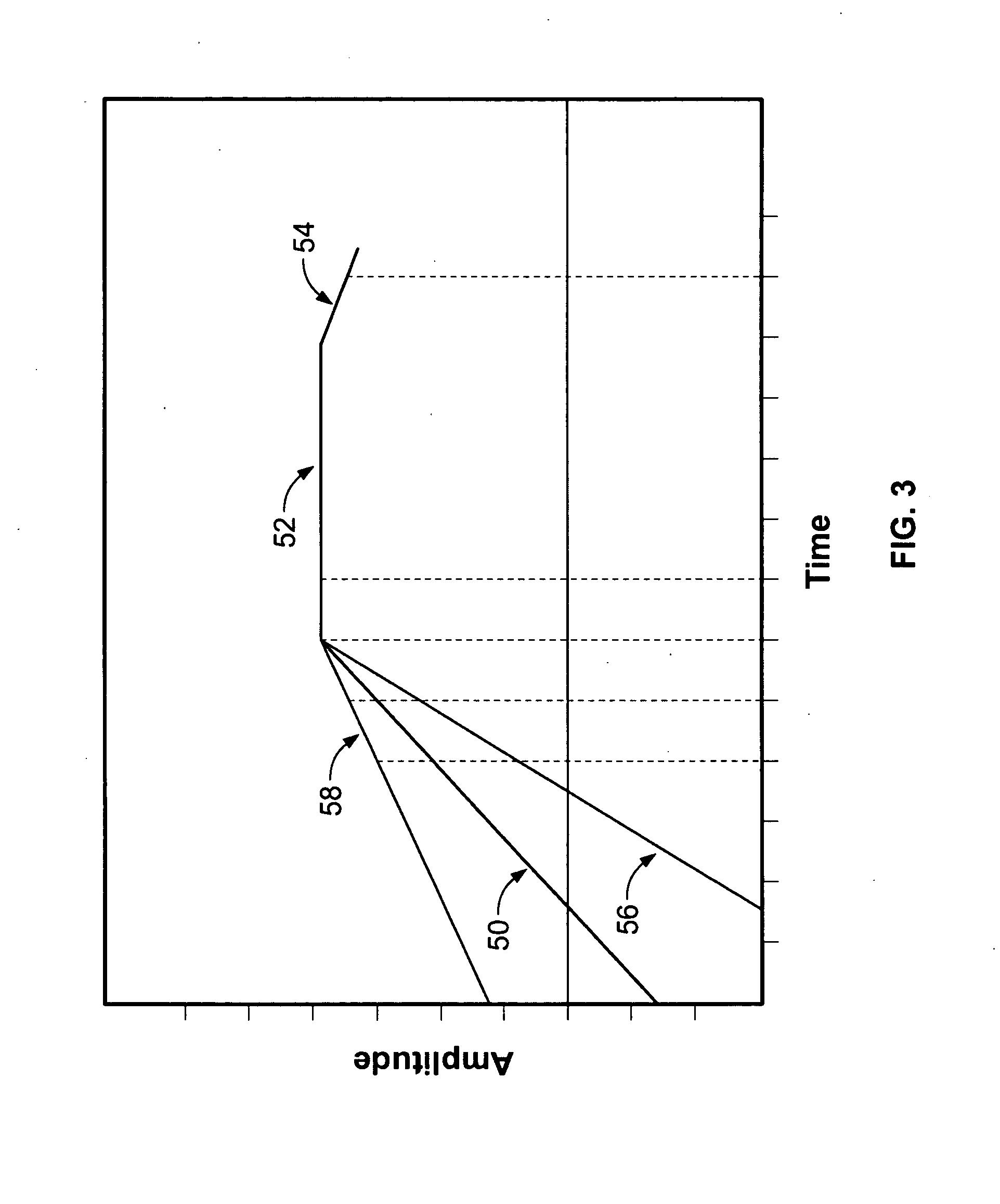
A a touch sensor including a keyboard having a key defining a touch sensing location, wherein the key is responsive to at least one of capacitive and electro-magnetic interactions with a user during a touch event includes control circuitry associated with the key, wherein the control circuitry outputs a control signal, and wherein an amplitude of the control signal is representative of an amount of interaction between the user and the key during a touch event. A controller is connected to the control circuitry and analyzes a variation in the amplitude of the control signal over a time period to identify the touch event.

Description

BACKGROUND OF THE INVENTION[0001]This invention relates generally to touch sensors, and more specifically, to touch detection methods and systems for touch sensors.[0002]Conventional touch sensing systems include a keyboard having multiple keys. Each key includes a conductive pad overlaid by a dielectric element. The conductive pad is connected to control circuitry that monitors the current level of the pad. Typically, the pad is supplied with a current having a constant amplitude, and when the key is touched by a user, the interaction between the user and the key changes the signal supplied to the key. By measuring an output signal of the key, the touch sensing system can detect when a touch event is occurring.[0003]One problem with conventional touch sensing systems is that the systems are sensitive to multiple factors that affect the output signals of the key. As such, the system may detect a faulty touch or the system may fail to detect an actual touch event. At least some of th...

Claims


Application Information

Patent Timeline
IPC IPC(8): G09G5/00
CPCH03K17/962
Inventor PAUN, TRAIAN RADUATANASSOV, FILIP
Owner TYCO ELECTRONICS CANADA
Why Eureka
Eureka Blog
Learn More