
Scissors

Inactive Publication Date: 2008-01-03
GEORGE
View PDF29 Cites 134 Cited by
  • Summary
  • Abstract
  • Description
  • Claims
  • Application Information

AI Technical Summary

Benefits of technology

[0007] An object of the present invention is to provide improved scissors which are robust, cut cleanly and effectively and avoid or minimise the disadvantages of current scissors as outlined above.
[0009] The restraining member resists splaying deflection of the blade members, which facilitates cutting of tough tissues such as ligaments.
[0010] There may be a clearance between the first blade member and the restraining member when the scissors are closed at the end of a cutting stroke, with the first blade member being narrower than the width of the slot or channel. In this way, the restraining member is not necessarily in contact with the first blade member during normal cutting but as soon as minor deflection of the first blade member takes up the clearance, the restraining member begins to limit further deflection.
[0011] It is also possible for the restraining member to bear against the first blade member during the cutting stroke. For example, the restraining member may bear resiliently against the first blade member to deflect resiliently as the first blade member moves during the cutting stroke. In this way, the restraining member can act continually to resist deflection of the first blade member. Indeed, the first blade member may be thicker or wider than the width of the slot or channel, so that resilient deflection of the restraining member is essential to accommodate the first blade member. In order to facilitate cleaning and sterilisation of the scissors, the restraining member may be circular in cross-section.
[0012] The second blade member and the restraining member may be conjoined along at least part of their shared length. For example, the second blade member and the restraining member may together define a U-shaped cross-section. This is stiff and easy to fabricate: for example, the second blade member and the restraining member may be formed integrally with one another. Alternatively, the second blade member and the restraining member may be separate along most of their shared length, for example being joined at opposed ends of the restraining member. This means that the second blade member and the restraining member can together define an open-bottomed slot, which is easier to clean and less likely to give rise to jamming.
[0017] For optimum cutting efficiency, the restraining member is preferably shorter than the second blade portion defining a difference in height at least equal to the width of the slot or channel between them.

Problems solved by technology

This conventional scissor design is ineffective when cutting tough fibrous tissue such as ligaments, or large sections of tissue.
In addition, the misalignment caused by the blade members splaying apart can result in tissue becoming trapped between the splayed blade members rendering the scissors useless until the trapped tissue is freed.
However, a series of small cuts, results in an imprecise, untidy and ragged cut; it also prolongs the procedure.
Often, surgical scissors are unable to withstand the rigours of surgery and sterilisation.
Commonly, the two blades are held against each other by a pivot pin which loosens and increases the risk of the blade splaying apart in use.
Also the blades tend to become blunt on recurrent use and hence require frequent sharpening.
However, thicker blades are both undesirable and impractical as the scissors may be too bulky to manoeuvre in confined spaces, heavier and therefore more tiring to use, and more expensive to make.

Method used


Image

  • Scissors
  • Scissors
  • Scissors

Examples


Embodiment Construction

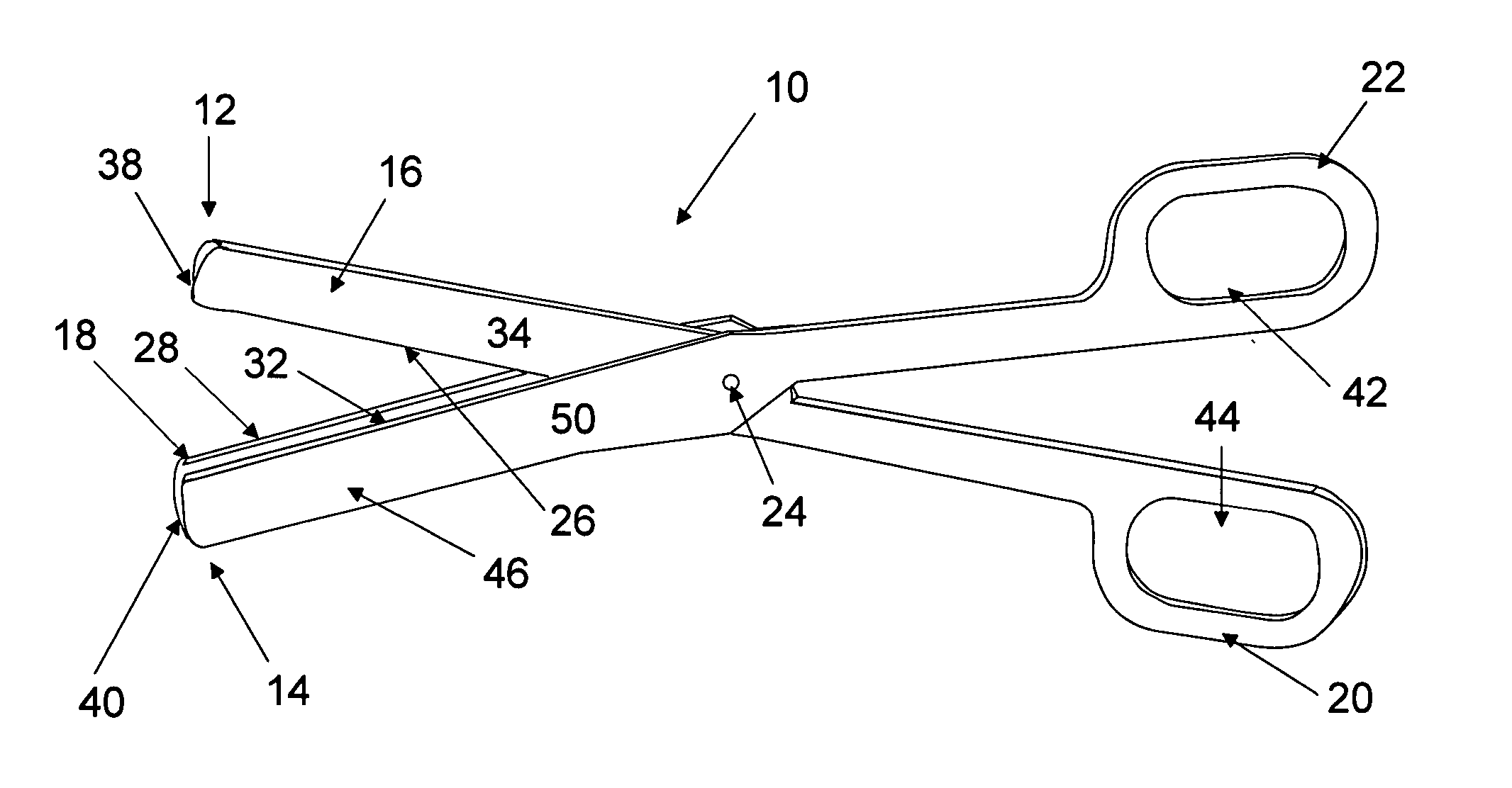
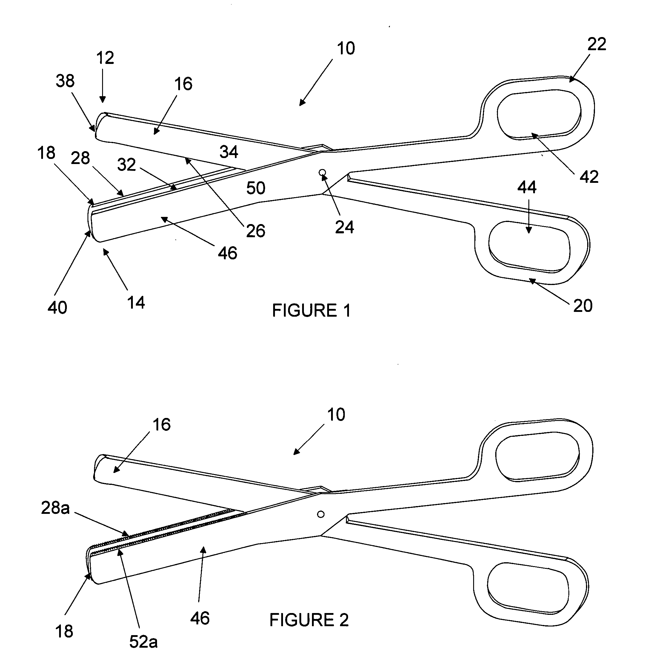
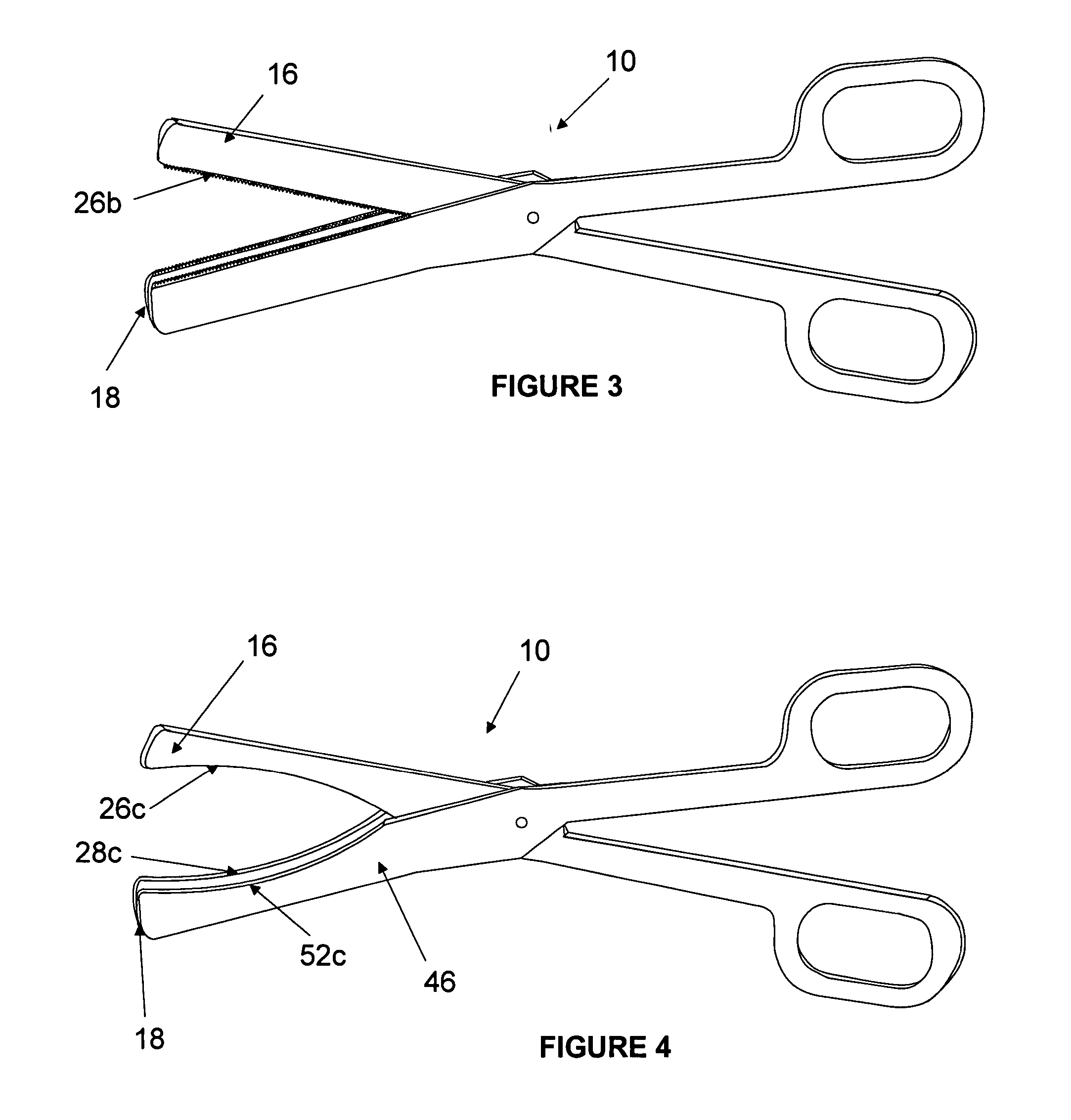
[0036] Referring firstly to FIG. 1, there is shown a pair of surgical scissors 10 having first and second elongate scissor members 12, 14. In conventional manner, each scissor member 12, 14 has a distal blade portion 16, 18 and a proximal handle portion 20, 22 and the scissor members 12, 14 are pivotally connected to each other by a rivet, screw, stud or pin 24 at a pivot axis between the blade portion 16, 18 and the handle portion 20, 22. Also conventionally, the blade portion 16, 18 has a cutting edge 26, 28, a contacting face 30, 32, an outer face 34, 36 and a distal tip 38, 40, and a finger opening 42, 44 is provided at the proximal end of the handle portion 20, 22.

[0037] Unconventionally, in accordance with the invention, a restraining member 46 is associated with the second blade portion 18 and may be integral with, or distinct from but attached to, the second blade portion 18. An integral restraining member 46 is shown in FIG. 1. The restraining member 46 is of substantially...


PUM


Abstract

The present invention are surgical scissors having first and second pivotably connected elongate blade members wherein the second blade member is associated with a restraining member extending at least partially along said blade member and spaced therefrom to define a slot or channel in which the first blade member is at least partially received during cutting to restrain relative lateral movement of the blade members away from each other during a cutting stroke. Further, the present invention are scissors bearing blade urging means upon a handle portion of the scissors urging handle portions apart during a cutting motion but thereby urging opposing scissor blades, with increasing pressure, together as the cutting motion proceeds.

Description

FIELD OF THE INVENTION [0001] The present invention relates to scissors and more particularly but not exclusively to surgical scissors. BACKGROUND OF THE INVENTION [0002] Surgical scissors are indispensable tools for surgeons, operating theatre staff and other medical practitioners and are used for cutting and excising patient tissue or sutures. These scissors need to be able to cut cleanly, effectively and accurately, to be robust, and to be suitable for sterilisation. It can be appreciated that accuracy of cutting is important in any surgical procedure. Achieving a clean cut is particularly important for minimising trauma and inflammation to the surrounding tissues. [0003] Conventional surgical scissors comprise two scissor members, each scissor member having a distal blade portion and a proximal handle portion. The blade portion has a cutting edge, a contacting face, an outer face and a distal tip. A finger opening is at the proximal end of the handle portion. The scissor members...

Claims


Application Information

Patent Timeline
IPC IPC(8): A61B17/32B26B13/06B26B13/08B26B13/20
CPCA61B17/3201B26B13/06A61B2019/4868B26B13/20B26B13/08A61B2090/0813
Inventor GEORGE
Owner GEORGE
Learn More