Glove
a glove and glove technology, applied in the field of gloves, can solve the problems of impaired feeling when gloves are put on, too stiff gloves, and inability to provide fitting,
- Summary
- Abstract
- Description
- Claims
- Application Information
AI Technical Summary
Benefits of technology
Problems solved by technology
Method used
Image

Examples
example 1
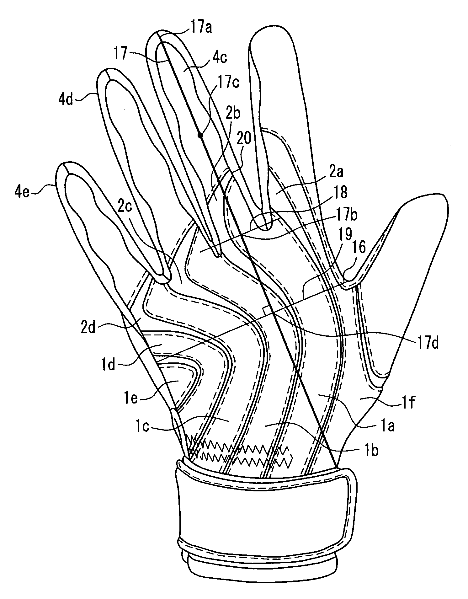
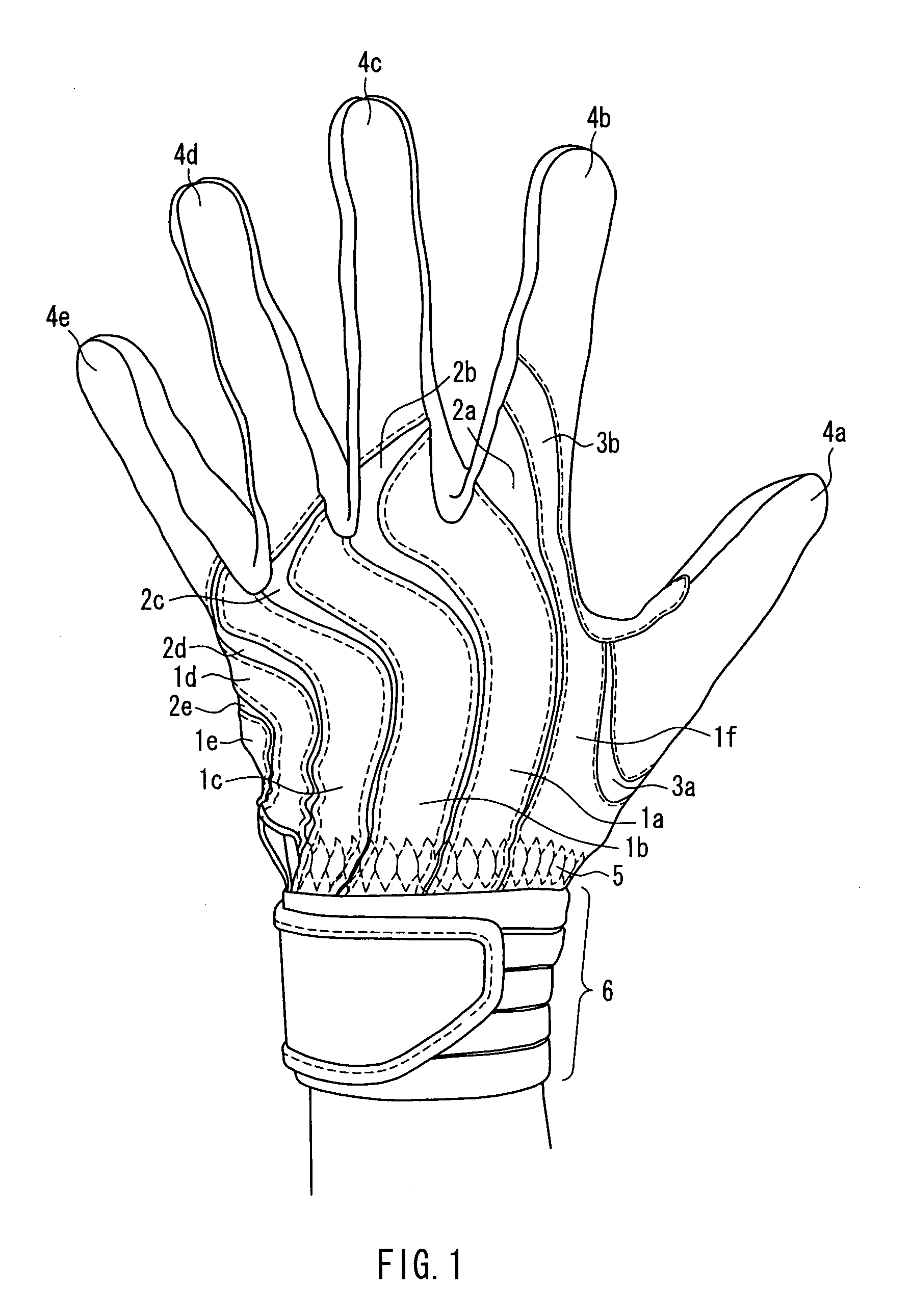
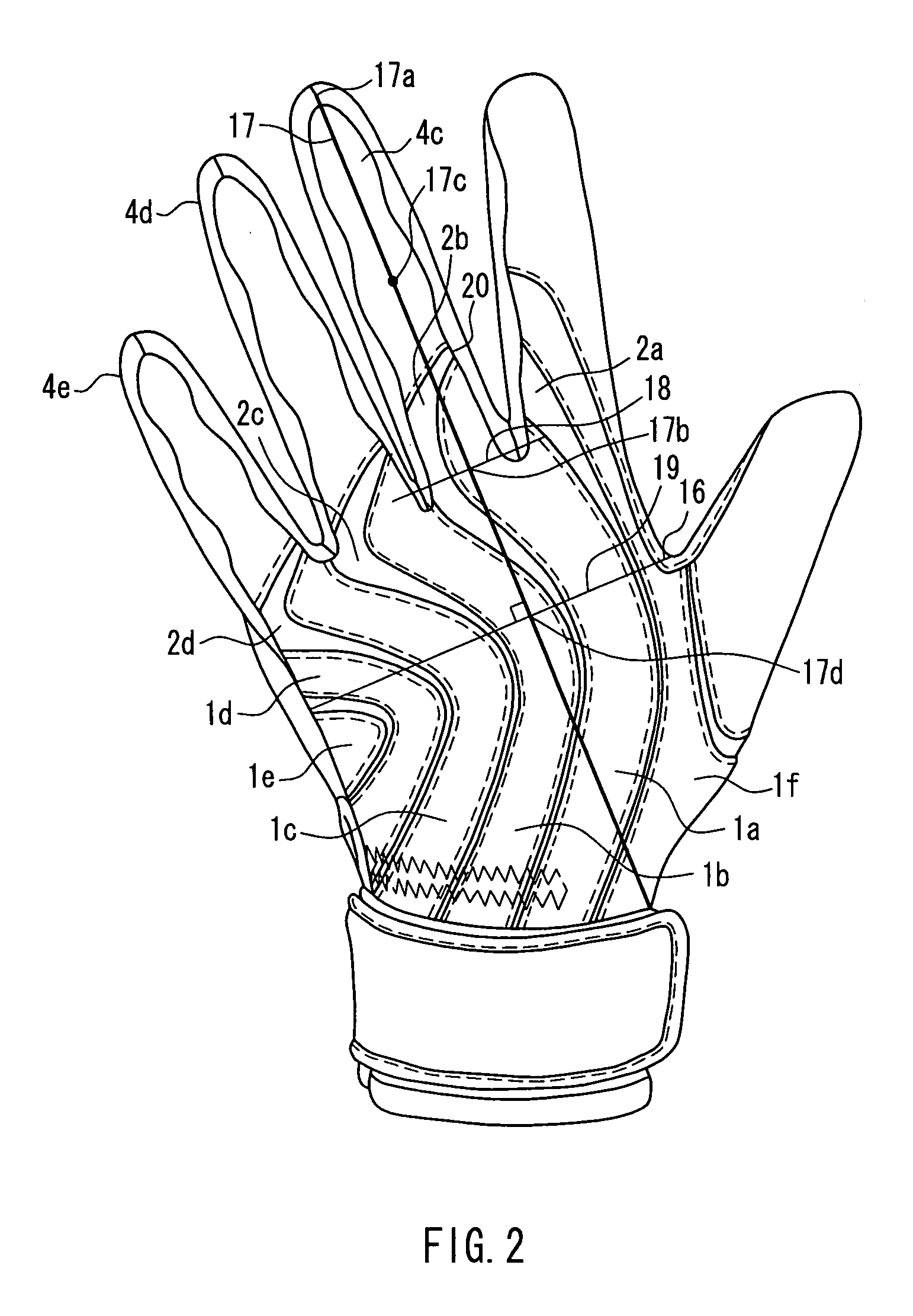
[0037]FIG. 1 shows a back side of a glove for use in baseball according to an example of the present invention. On a back part of this glove, protective members (1a to 1c) were configured to be three or more separate linear pieces made of a natural leather, a synthetic leather, or an artificial leather. Additional protective members (1d to 1e) were provided on the little finger side to the foregoing three linear pieces, and an additional protective member (1f) was provided on the thumb side to the three linear pieces. As shown in FIG. 2 that shows the glove placed in a stationary state and viewed from the back side, four separate curve surfaces whose upper ends were located at certain positions in lower half parts of finger covering parts (4b to 4e) were formed with a stretchable member (2a to 2d). Each of the curve surfaces formed with the stretchable member was extended toward the wrist, crossing each center line of the finger covering parts at least twice in a region from the upp...
example 2
[0056]A glove was formed in the same manner as that of Example 1 except that the strap 16 for the wrist was omitted. The glove is shown in FIG. 6. FIG. 6 shows a back side of the glove for use in golf according to Example 2 of the present invention. This glove was used in playing golf, and it was recognized that the glove was capable of following changes in shape of the back of the hand in an area from the vicinities of the proximal phalanx to the vicinities of the middle phalanxes, providing both of the feeling of fitting and the feeling of support, and maintaining a high-level protection function and a high-level mobility function, as in Example 1. In other words, the stretchable members were stretched in the longitudinal, lateral, and oblique directions in response to significant changes in the shape of the hand, whereby the glove was capable of following the changes in the shape of the hand while maintaining fit to the entirety of the hand, and allowing the hand to assume a grip...
example 3
[0057]FIG. 7 shows a glove of Example 1 in which notch-like portions (3a to 3e) formed with stretchable members were provided additionally in the back portions of the finger covering parts, so as to be parallel with the first arcs, at positions corresponding to capitular parts of the middle phalanxes. This configuration allowed the glove further to follow significant changes in shape at the capitular parts of the middle phalanxes.
PUM
 Abstract
Description
Claims
Application Information
 - R&D
- Intellectual Property
- Life Sciences
- Materials
- Tech Scout
- Unparalleled Data Quality
- Higher Quality Content
- 60% Fewer Hallucinations
Browse by: Latest US Patents, China's latest patents, Technical Efficacy Thesaurus, Application Domain, Technology Topic, Popular Technical Reports.
© 2025 PatSnap. All rights reserved.Legal|Privacy policy|Modern Slavery Act Transparency Statement|Sitemap|About US| Contact US: help@patsnap.com