
Inflatable boat

a technology for inflatable boats and boats, which is applied in the field of inflatable boats, can solve the problems of boat trim, slow inflation or deflation process when performed from a single point, and loss of head, etc., and achieve the effects of improving the frequency, facilitating maintenance, and accelerating the operation of inflatable boats

Inactive Publication Date: 2007-12-27
Z MARINE INT
View PDF5 Cites 6 Cited by
  • Summary
  • Abstract
  • Description
  • Claims
  • Application Information

AI Technical Summary

Benefits of technology

"The invention proposes an improved solution for inflating and deflating a boat by combining the benefits of previous solutions, such as faster operations and more efficient use of intercommunication valves. The invention provides an inflatable boat with at least two pneumatic chambers, a device for distributing gas under pressure, and a drive means for simultaneously inflating or deflating the chambers. The technical effects of the invention include faster and more complete inflation and deflation of the boat, improved safety, and economic and safety advantages."

Problems solved by technology

One drawback of such an arrangement lies in the slowness of the inflation or deflation process when performed from a single point, since it is the entire volume of gas in the float that must pass through the single point.
In addition, the distance between said single point (even when located in the center of the float) and the furthest points of a float remains large, particularly for boats of large dimensions; furthermore, the presence of a plurality of intercommunication valves through a plurality of partitions leads to head losses that slow down the propagation of gas.
Thus, the float does not inflate or deflate in a manner that is substantially uniform overall, so the boat does not keep its trim during these operations.
Another drawback lies in the fact that the intercommunication valves are expensive devices.
This equipment is therefore costly in an inflatable boat (which in practice can have as few as three or as many as seven or eight intercommunication valves depending on its dimensions and the number of compartments).
Yet another drawback lies in the fact that an intercommunication valve can be left in the open position (so that two adjacent compartments remain pneumatically interconnected) by inadvertence (closing forgotten, accidental opening), which can affect the buoyancy of the boat in the event of these compartments that have remained interconnected being deflated accidentally.
This can become catastrophic if all of the intercommunication valves of a boat remain in the open position.
Yet another drawback lies in the fact that since the intercommunication valves are enclosed within the float, they are not accessible from the outside.
If action needs to be taken on them (repair, replacement), it is necessary to open the float, and then after taking that action, to reclose the float in airtight manner, which constitutes an operation that is lengthy and difficult, and that can be performed only in a workshop.
Nevertheless, those arrangements with completely independent compartments still present drawbacks.
A major drawback lies in the length of time required for inflation or deflation, and the multiplicity of handling operations needed for connecting the pump endpiece to all of the valves in succession.
In addition, because of the need to inflate and / or deflate the compartments in succession, the boat does not maintain its trim while these operations are taking place.

Method used


Image

  • Inflatable boat
  • Inflatable boat
  • Inflatable boat

Examples


Embodiment Construction

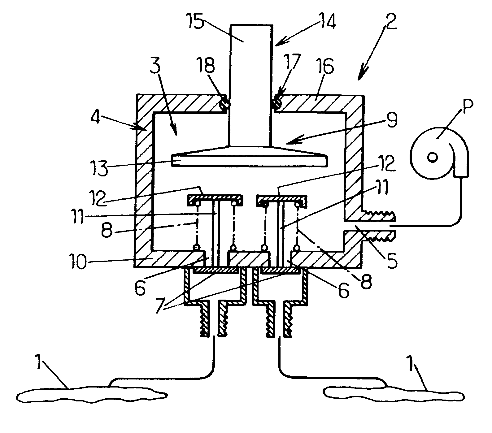
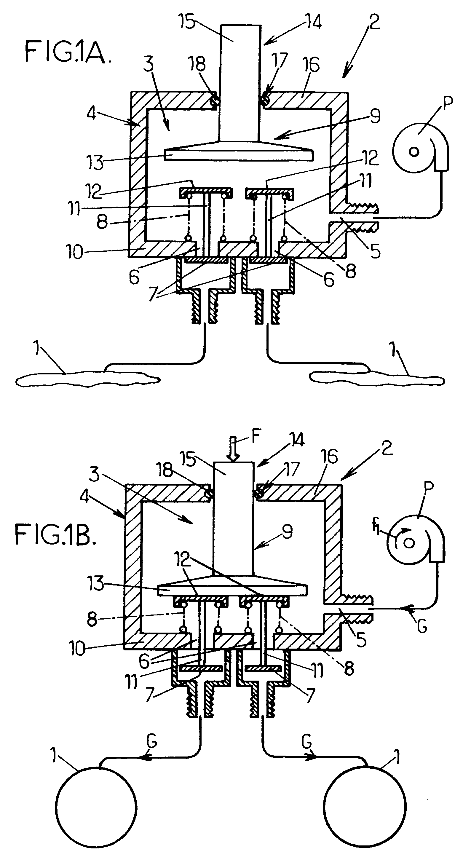
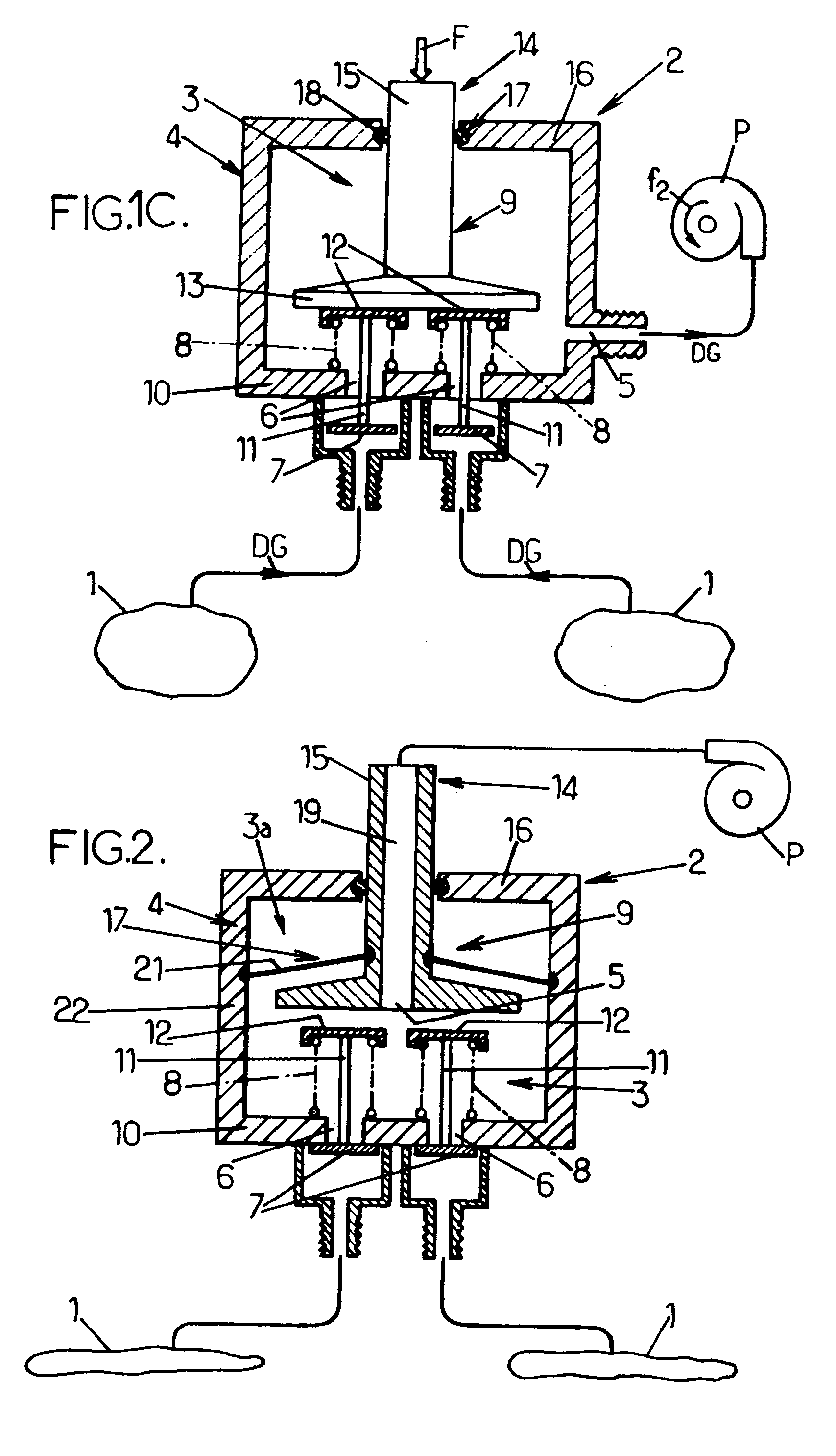
[0051]Reference is made initially to FIG. 1A which is a diagram showing one arrangement for an inflatable boat in accordance with the invention. In this diagram, only those elements that are needed for understanding the invention are shown, while the boat itself is not shown explicitly since its overall design is not involved in any essential manner in the fundamental design of the invention.

[0052]In the invention, the inflatable boat has at least two inflatable chambers 1 that need to be inflated with gas at the same pressure (typically compressed air); in FIG. 1A, the boat is represented merely by two chambers 1.

[0053]The boat also includes a device 2 for distributing gas under pressure, which device comprises an enclosure 3 that is closed in airtight manner and defined by a case or box 4 designed in any suitable manner in association with its function and its installation in the boat; this case can be made in particular out of molded synthetic material, and an example is illustra...


PUM


Abstract

An inflatable boat possessing at least two inflatable chambers (1) and a device (2) for distributing gas under pressure, the device comprising: a leaktight enclosure (3) possessing a first orifice (5) and at least two second orifices (6) connected to said chambers (1); at least two closure valves (7) associated respectively with the two second orifices (6) and normally urged into a position for closing the respective second orifices (6); and means (9) for simultaneously driving all of the closure valves (7) selectively in the opening direction or in the closing direction; this makes it possible to control simultaneous inflation or deflation of all the inflatable chambers (1).

Description

FIELD OF THE INVENTION [0001]The present invention relates to the general field of inflatable boats, and more particularly it relates to improvements applied to inflating and / or deflating such boats when they include at least two inflatable chambers.[0002]Although the invention relates to all types of inflatable chamber with which an inflatable boat might be equipped, it relates in more particularly advantageous manner to inflating and / or deflating the inflatable float(s) with which such boats are equipped. For reasons of safety, such inflatable floats are subdivided by internal partitions into a plurality of compartments in such a manner that if one compartment should become deflated by accident, the other compartments are not affected and the boat continues to be buoyant.BACKGROUND OF THE INVENTION [0003]It is known to fit the internal partitions with intercommunication means (intercommunication valves) suitable for being put into an open position so as to put two adjacent compart...

Claims


Application Information

Patent Timeline
Patent Type & Authority Applications(United States)
IPC IPC(8): B63B7/00
CPCB63B7/085F16K15/20F16K15/18F16K15/202B63C9/24
Inventor ZEROMSKI, DOMINIQUE
Owner Z MARINE INT
Learn More