
Castor having efficiently locking function

a technology of efficient locking and castors, applied in the field of castors, can solve problems such as inconvenience for users, and achieve the effect of efficient locking function

Inactive Publication Date: 2007-12-20
TSAI PO CHUAN
View PDF7 Cites 24 Cited by
  • Summary
  • Abstract
  • Description
  • Claims
  • Application Information

AI Technical Summary

Benefits of technology

[0008]The primary objective of the present invention is to provide a castor having an efficiently locking function.
[0009]Another objective of the present invention is to provide a castor, wherein when the stop member is movable downward to rest on the ground, the two rollers are suspended in the air, so that the castor is locked exactly without slipping or moving on the ground.

Problems solved by technology

However, when the two rollers 10 are locked by the locking rod 13 of the control member 11, the two rollers 10 are still rested on the ground, so that the castor easily slips on the ground by applying a pulling force on the castor, thereby causing inconvenience to the user.

Method used


Image

  • Castor having efficiently locking function
  • Castor having efficiently locking function
  • Castor having efficiently locking function

Examples


Embodiment Construction

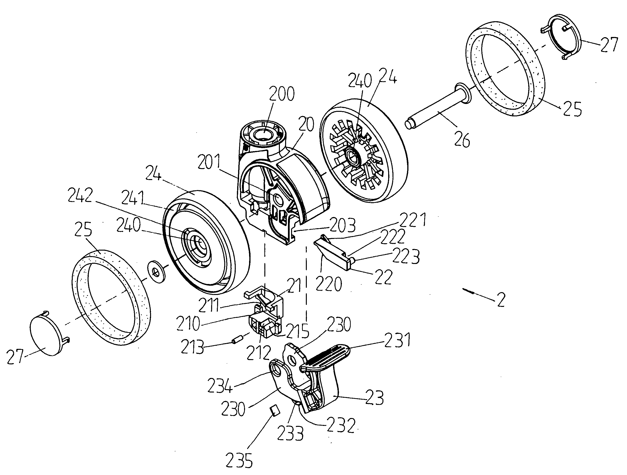
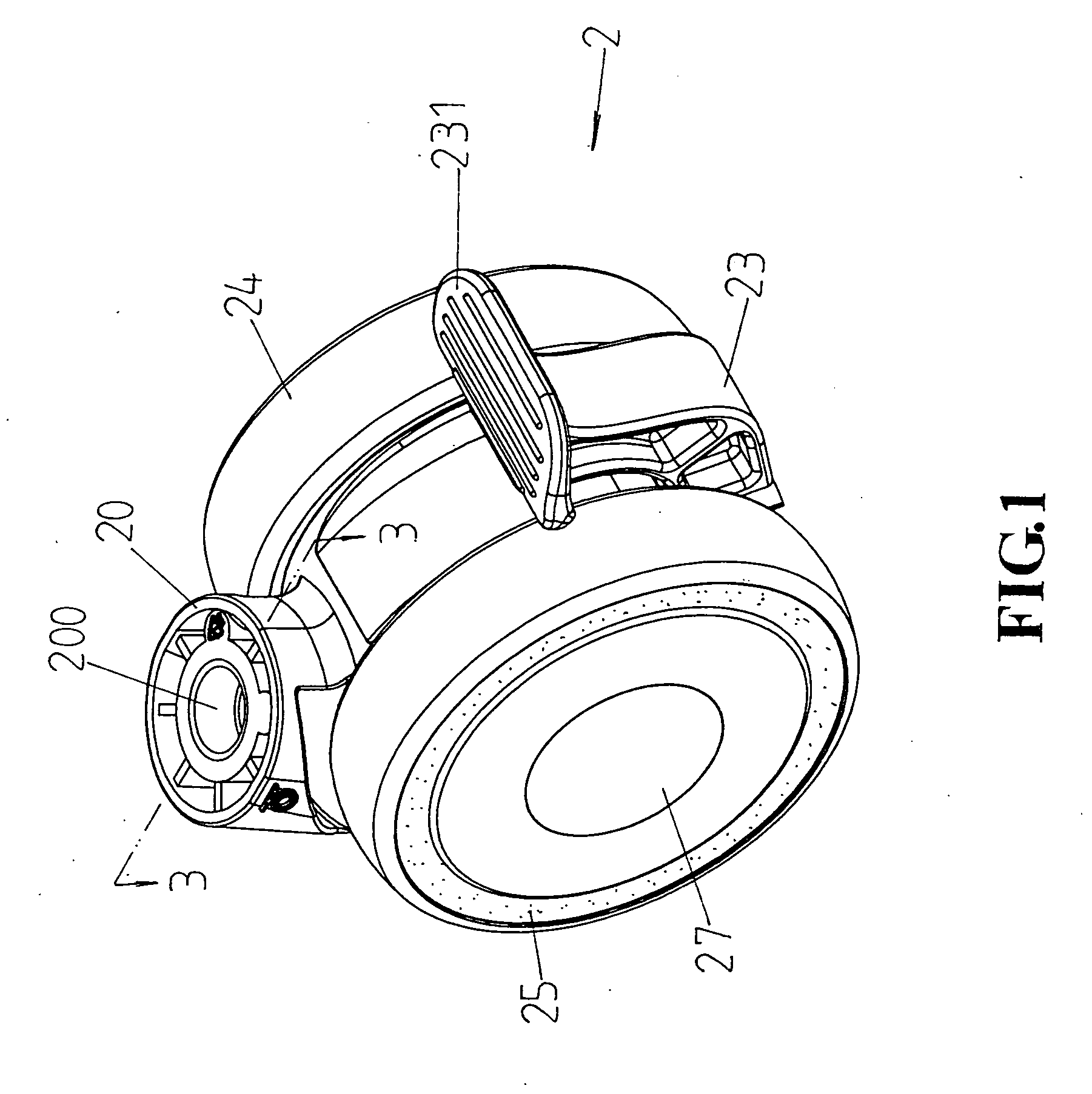
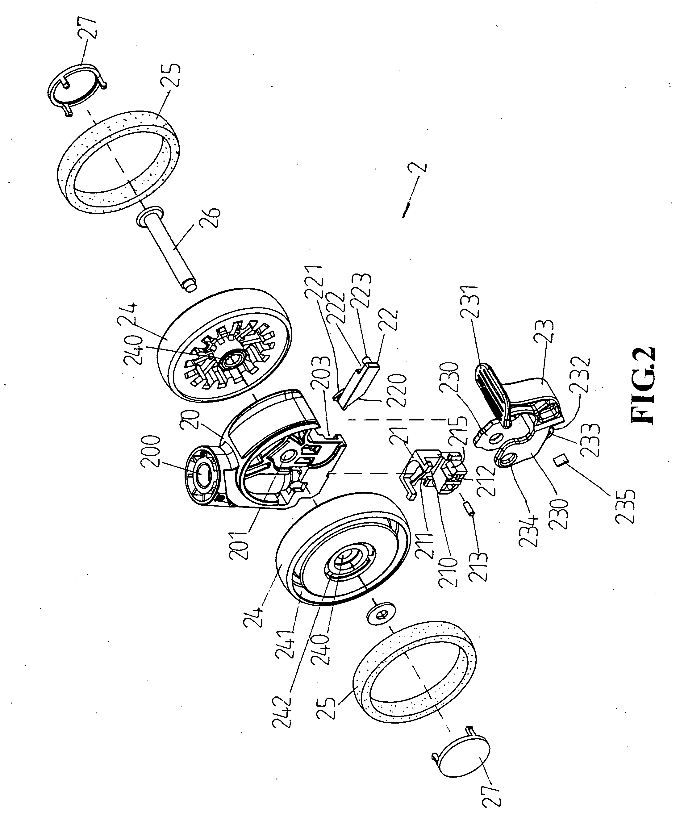
[0018]Referring to the drawings and initially to FIGS. 1-3, a castor in accordance with the preferred embodiment of the present invention comprises a main body 20, two rollers 24 each rotatably mounted on the main body 20, a stop member 21 movably mounted in the main body 20 and movable between a first position as shown in FIG. 3 where the stop member 21 is located at a height higher than that of each of the two rollers 24 and a second position as shown in FIG. 4 where the stop member 21 is located at a height lower than that of each of the two rollers 24, a slide 22 slidably mounted in the main body 20 and rested on the stop member 21 to move the stop member 21, and a control member 23 pivotally mounted on the main body 20 and connected to the slide 22 to move the slide 22.

[0019]The main body 20 has a bottom formed with a slideway 203 to allow movement of the slide 22 and a receiving chamber 202 (see FIG. 3) connected and perpendicular to the slideway 203 to allow movement of the s...


PUM


Abstract

A castor includes a main body, two rollers each rotatably mounted on the main body, a stop member movable in the main body between a first position where the stop member is located at a height higher than that of each of the two rollers and a second position where the stop member is located at a height lower than that of each of the two rollers, a slide slidably mounted in the main body to move the stop member, and a control member pivotally mounted on the main body to move the slide. Thus, when the stop member is movable downward to rest on the ground, the two rollers are suspended in the air, so that the castor is locked exactly without slipping or moving on the ground.

Description

BACKGROUND OF THE INVENTION[0001]1. Field of the Invention[0002]The present invention relates to a castor and, more particularly, to a castor for a chair and the like.[0003]2. Description of the Related Art[0004]A conventional castor in accordance with the prior art shown in FIGS. 6 and 7 comprises a main body 1, two rollers 10 each rotatably mounted on the main body 1 and each having an inside formed with a locking slot 12, and a control member 11 pivotally mounted on the main body 1 and provided with a locking rod 13 movable in the locking slot 12 of each of the two rollers 10.[0005]In operation, when the control member 11 is located at the position as shown in FIG. 6, the locking rod 13 of the control member 11 is located at the lower end of the locking slot 12 of each of the two rollers 10, so that the two rollers 10 are rotatable freely, and the castor is movable on the ground. On the contrary, when the control member 11 is located at the position as shown in FIG. 7, the lockin...

Claims


Application Information

Patent Timeline
Patent Type & Authority Applications(United States)
IPC IPC(8): B60B33/00
CPCB60B33/0042B60B33/0049B60B33/0057B60B33/0068B60B33/0073Y10T16/195B60B33/021B60B33/023Y10T16/1937Y10T16/18B60B33/0089
Inventor TSAI, PO-CHUAN
Owner TSAI PO CHUAN
Learn More