
Image display device

a technology of image display and display screen, which is applied in the field of image display device, can solve the problems of not necessarily and sufficiently reflecting the watcher's gaze, and the watcher's fatigue feeling is caused, and achieve the effect of reducing the electric-power consumption and reducing the watcher's fatigu

Active Publication Date: 2007-12-13
MITSUBISHI ELECTRIC CORP
View PDF4 Cites 22 Cited by
  • Summary
  • Abstract
  • Description
  • Claims
  • Application Information

AI Technical Summary

Benefits of technology

The present invention provides an image display device that controls the brightness of the display screen based on the environmental brightness level and the watcher's characteristics such as visual acuity, age, and viewing distance. This ensures that the display is always bright enough to suit the watcher's preference and reduces the tiredness of the watcher. Additionally, controlling the brightness of the screen also helps to reduce electric-power consumption.

Problems solved by technology

Therefore, the glare feeling that a watcher feels is caused not only by light from the image display device, but also by that from the background region of the device.
Therefore, the conventional method, in which only the environmental brightness level is measured, and the brightness level of the display device is controlled, can neither necessarily nor sufficiently reflect the watcher's preference.

Method used


Image

  • Image display device
  • Image display device
  • Image display device

Examples


embodiment 1

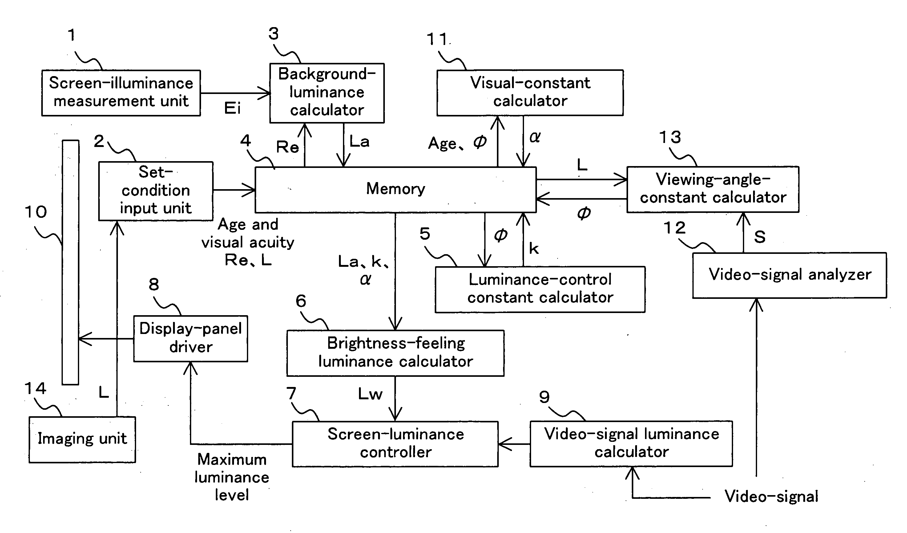
[0018]FIG. 1 is a block diagram representing a configuration of an image display device according to Embodiment 1 of the present invention. The image display device according to Embodiment 1 includes a screen-illuminance measurement unit 1, a set-condition input unit 2, a background-luminance calculator 3, a memory 4, a luminance-control constant calculator 5, a brightness-feeling luminance calculator 6, a screen-luminance controller 7, a display-panel driver 8, a video-signal luminance calculator 9, a display screen 10, a visual-constant calculator 11, a video-signal analyzer 12, a viewing-angle-constant calculator 13, and an imaging unit 14. Here, hereinafter, the background-luminance calculator 3, the luminance-control constant calculator 5, the brightness-feeling luminance calculator 6, the visual-constant calculator 11, and the viewing-angle-constant calculator 13 may also be collectively called as a calculator.

[0019] The screen-illuminance measurement unit 1 is a light receiv...

embodiment 2

[0040]FIG. 5 is a plot of results that the screen illuminance Ei and the background luminance La are measured in each room, where a television set is placed, of 50 general homes. Straight lines are drawn in FIG. 5 when the factors Re in Equation (1) are “1.0” and “0.2”. In general home environment, by setting the background-luminance factor Re to a value not larger than 1.0, the entire home environment can be reflected. Moreover, in general environment, it can also be found to be suitable when using 0.2 as the factor.

[0041] By fixing the background-luminance factor Re, calculation using the background-luminance calculator 3 can be simplified, or the background-luminance calculator 3 can also be omitted.


PUM

PropertyMeasurementUnit
luminanceaaaaaaaaaa
luminanceaaaaaaaaaa
luminanceaaaaaaaaaa

Abstract

A display device is provided that controls, considering affection due to a watcher's age and his viewing distance as human-visual characteristics, a display-screen brightness level at which the watcher does not feel glare. The display-screen brightness is most suitably set by simple calculation using relationships among watcher's ages, display sizes, glare levels, and screen-illuminance levels, etc. obtained by a subjective-assessment experiment. According to this display device, considering watcher's various conditions such as the age, the visual acuity, and the viewing distance, even if the watcher watches the display for a relatively long time, the watcher does not feel tiredness; thus, comfortable watching can be achieved.

Description

BACKGROUND OF THE INVENTION [0001] 1. Field of the Invention [0002] The present invention relates to image display devices. [0003] 2. Description of the Prior Art [0004] Recently, in television sets used in general homes, a flat-panel display such as a liquid-crystal display device or a plasma display device has become popular instead of a Braun-tube display. The technology of a high-luminance flat-panel display has progressed with the improvement of device performance. However, although the technology of a high-luminance display device improves the visibility thereof, the technology has also led an important cause of tiredness or eye-fatigue due to glare feeling. [0005] Moreover, a problem has also occurred that the cost of electric-power consumption increases with the high luminance of the liquid-crystal display device or the plasma display device. [0006] Accordingly, a method is generally used in which, by installing into a display device a light receiving element for measuring t...

Claims


Application Information

Patent Timeline
Patent Type & Authority Applications(United States)
IPC IPC(8): H04N5/445G02F1/133G09G3/20G09G3/36G09G5/00G09G5/10H04N5/57H04N5/66H04N17/04
CPCH04N5/58H04N21/42202H04N21/44218H04N21/4318H04N21/44008H04N21/4223
Inventor NAKAMURA, YOSHITOMOYAMAKAWA, MASAKIKIDO, EMIKOKUBOTA, SATORU
Owner MITSUBISHI ELECTRIC CORP
Learn More