Liquid discharge head

a liquid discharge head and liquid discharge technology, applied in printing and other directions, can solve the problems of lowering the strength of the substrate, deformation or breakage, etc., and achieve the effect of high reliability and low cos

Inactive Publication Date: 2007-12-06
CANON KK
View PDF7 Cites 4 Cited by
  • Summary
  • Abstract
  • Description
  • Claims
  • Application Information

AI Technical Summary

Benefits of technology

[0025]An object of the present invention is to provide an inexpensive and highly reliable liquid discharge head, that is free from a cracking in a substrate, even when a periphery of a liquid discharge substrate, employed in the liquid discharge head, is sealed with a thermosetting resin.

Problems solved by technology

This phenomenon becomes a trouble in producing the recording element substrate of a lowered strength, which results for example by minimizing the size of the recording element substrate for the purpose of cost reduction.
Therefore, in the case that the recording element substrate 801 is exposed to a temperature environment, extremely different from the temperature at which the recording element substrate 801 was fixed to the support substrate 802 of resinous material, the recording element substrate 801 is subjected to a deformation stress of the resin and may cause defects such as a deformation or a breakage.

Method used


Image

  • Liquid discharge head
  • Liquid discharge head
  • Liquid discharge head

Examples


first exemplary embodiment

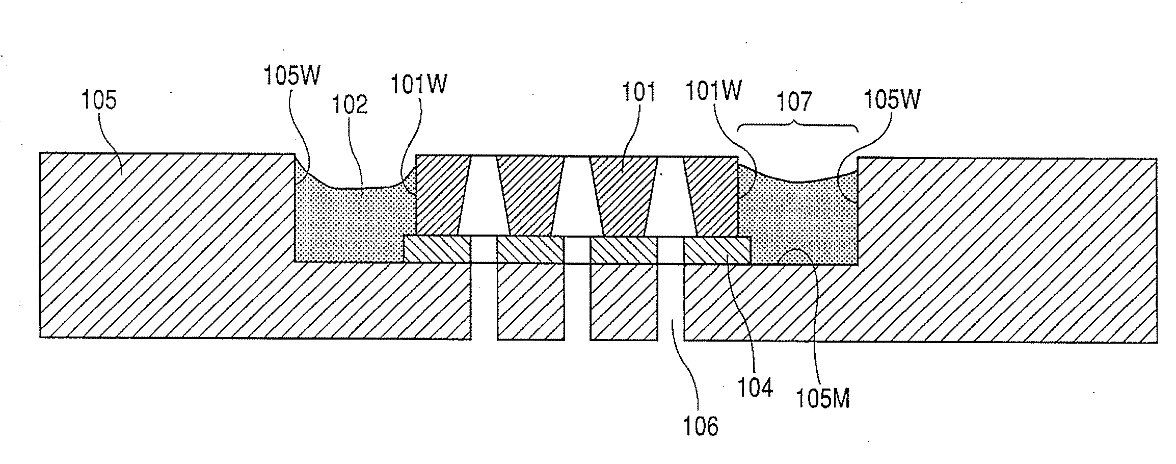
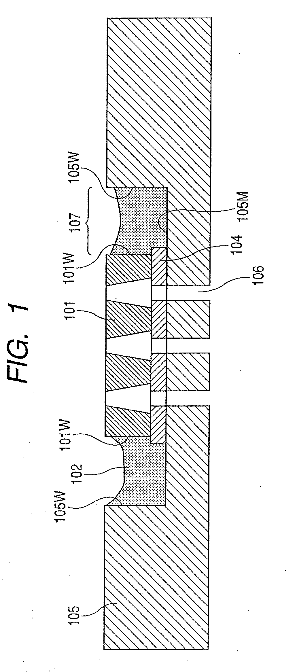
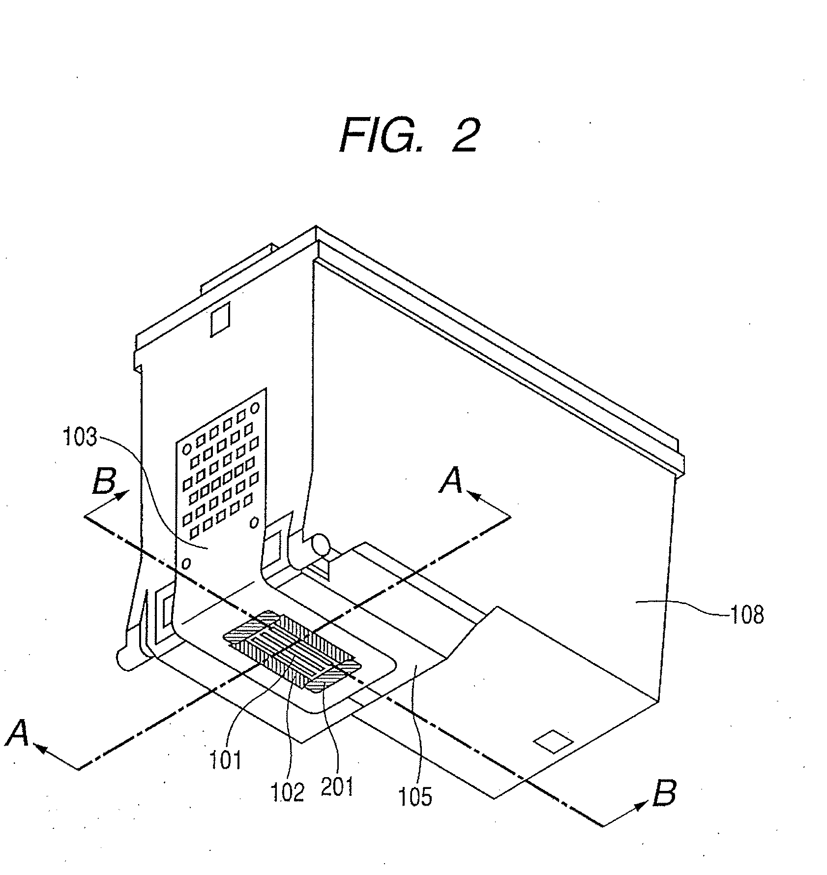
[0039]FIG. 1 is a schematic partial cross-sectional view illustrating a recording element substrate 101 of an ink jet head, in a first exemplary embodiment of the present invention, and illustrates a cross section along a line A-A in FIG. 2. FIG. 2 is a perspective view of an ink jet head cartridge 100 of the present exemplary embodiment. In FIG. 2, a direction along a line B-B is parallel to a direction of array of ink discharge ports, constituting a discharge port array of the ink jet head. Also a direction along the line A-A in FIG. 2 is perpendicular to the line B-B.

[0040]The ink jet head cartridge 100 of the present exemplary embodiment includes a flow path member 105, which supports the recording element substrate 101 across a support substrate 104, and which includes an ink flow path for supplying the recording element substrate 101 with an ink from an ink container portion 108 containing the ink. The recording element substrate 101 is prepared with a silicon substrate and is...

second exemplary embodiment

[0061]Now a second exemplary embodiment will be described with reference to FIG. 6, in which components same as those in the foregoing embodiment will be represented by same symbols.

[0062]Referring to FIG. 6, the recording element substrate 101 is adhered and fixed, across a support substrate 506 made of alumina, by an adhesive material to the flow path member 105 made of a resin. In the present exemplary embodiment, a case 108 is an ink container incorporating an ink absorbent member (not illustrated) impregnated with ink, and is prepared by a resin molding integrally with the flow path member 105. An electrical wiring tape 103 is electrically connected to the recording element substrate 101, and transmits an electrical signal from the ink jet recording apparatus (not illustrated) to the recording element substrate 101.

[0063]The recording element substrate 101 has a construction including discharge port arrays, for discharging ink of three colors of yellow, magenta and cyan, in thi...


PUM


Abstract

A liquid discharge head includes a liquid discharge substrate containing an energy generating element and a liquid discharge port, a flow path member of a resinous material fixed to the liquid discharge substrate and having at least a liquid supply path, a sealing material of a resinous material, a concave part, and a support substrate, wherein a distance L1 from a lateral face of the concave part of the flow path member to an end of the support substrate, a distance L2 from the lateral face of the concave part to a lateral face of the liquid discharge substrate, a linear expansion coefficient E1 of the flow path member and a linear expansion coefficient E2 of the sealing material satisfy a relation: L1×E1>L2×E2.

Description

BACKGROUND OF THE INVENTION[0001]1. Field of the Invention[0002]The present invention relates to a liquid discharge head for discharging a liquid.[0003]2. Description of the Related Art[0004]An example of the liquid discharge head, popularly used recently is an ink jet head. In general, the ink jet head includes a recording element substrate serving as a liquid discharge substrate for discharging the liquid, and an ink supply system for supplying such recording element substrate with an ink as a liquid.[0005]Also such ink jet head is available in a tank-replaceable type in which an ink tank and an ink jet head are made detachable, and in an ink jet head cartridge type in which an ink jet head part and an ink container part, containing ink, are constructed integrally.[0006]In the following, a conventional ink jet head will be described with reference to FIGS. 9A and 9B. The description will be made on an example of a color cartridge, for executing printing by discharging inks of yell...

Claims


Application Information

Patent Timeline
Patent Type & Authority Applications(United States)
IPC IPC(8): B41J2/015
CPCB41J2/14024
Inventor TSUKUDA, KEIICHIRO
Owner CANON KK
Why Eureka
Try Eureka