Spiked Barrier
- Summary
- Abstract
- Description
- Claims
- Application Information
AI Technical Summary
Benefits of technology
Problems solved by technology
Method used
Image

Examples
Embodiment Construction
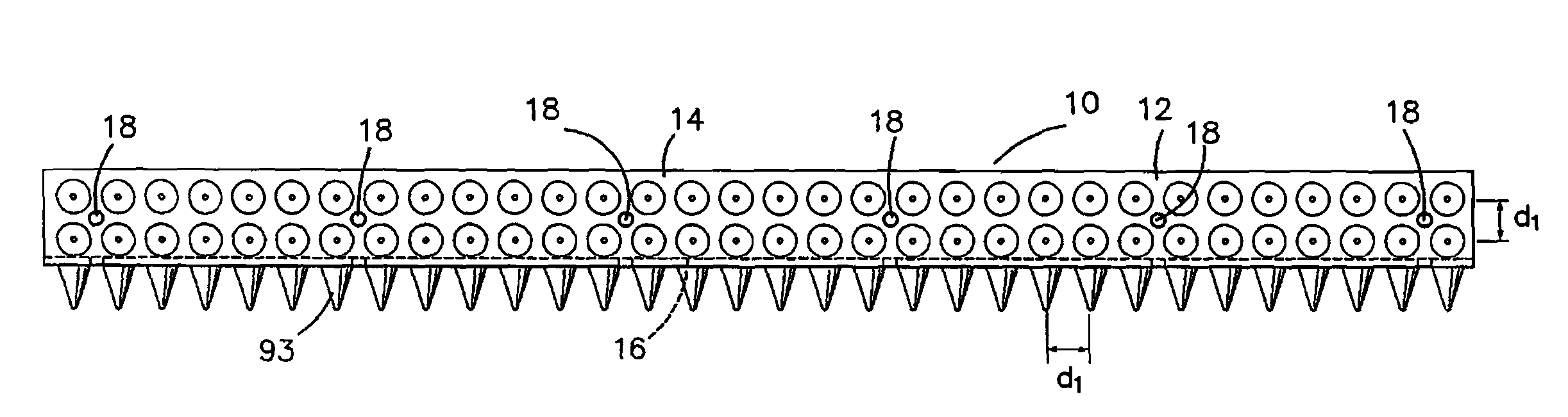
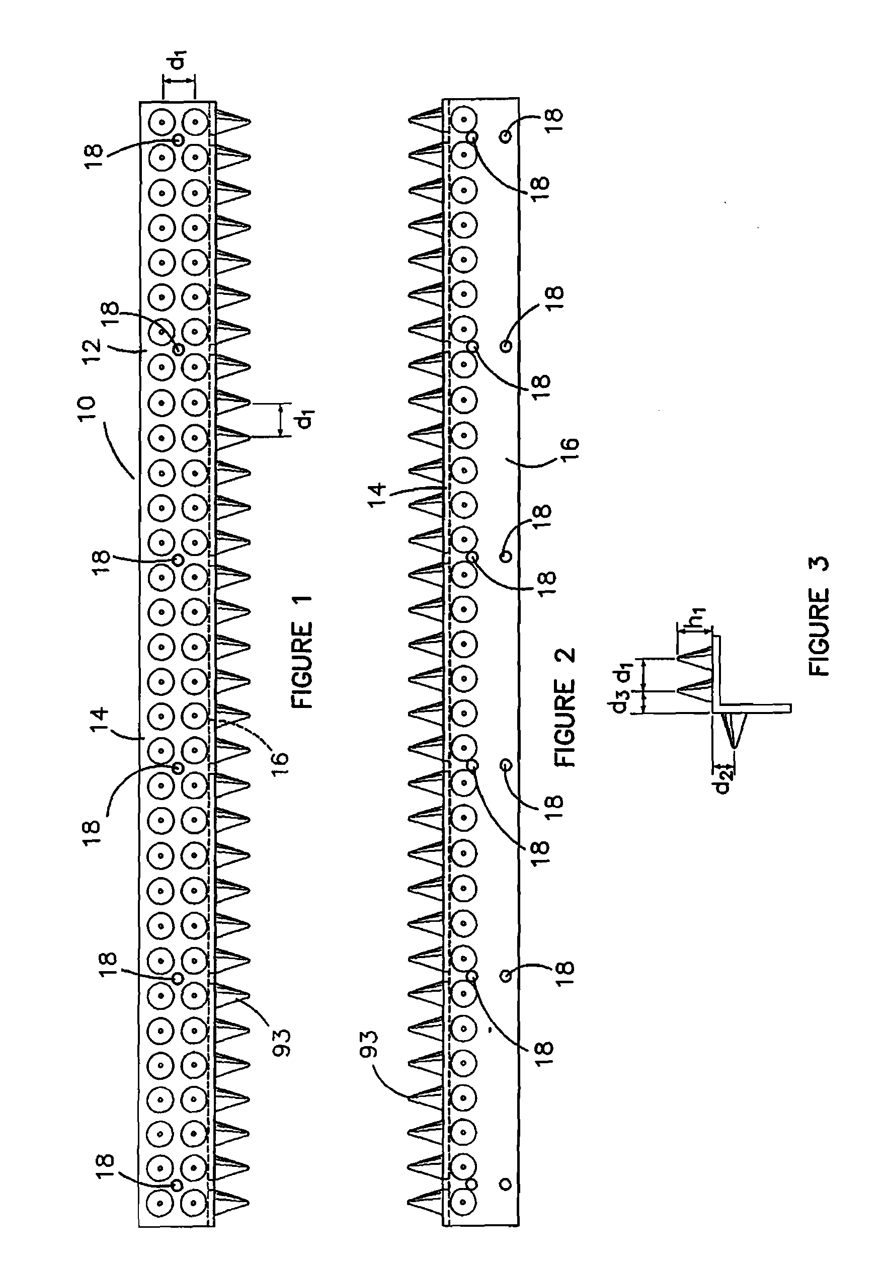
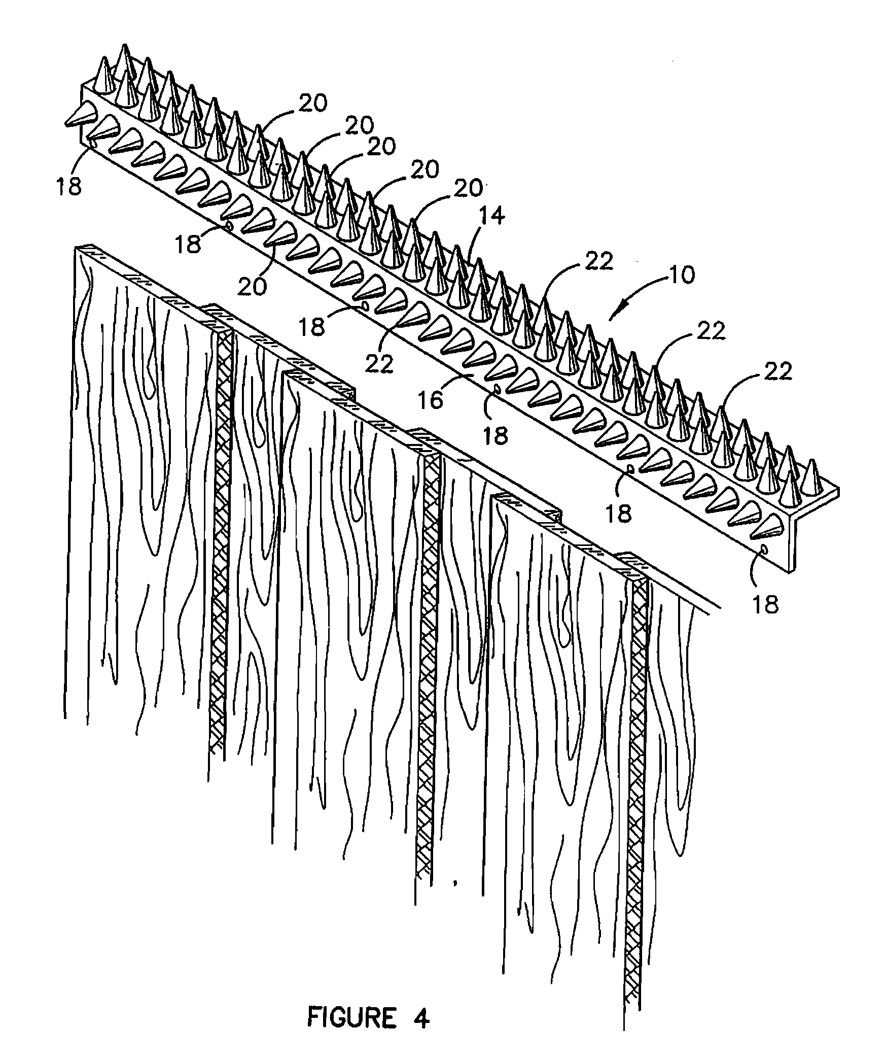
[0109] With reference to FIGS. 1 to 4, one embodiment of a spiked barrier 10 is shown which comprises a base 12 formed from an angled section having a first portion 14 and a second portion 16 arranged at a 90° angle to the first portion 14. The portions 14 and 16 have holes 18 for receiving fasteners such as nails or screws to secure the barrier 10 to a structure such as a paling fence shown in FIG. 4. Alternatively, an adhesive may be used to fasten the spiked barrier 10 to a structure. Adhesion is improved by allowing adhesive to flow into the holes 18 and to cure.
[0110] In FIG. 4, nails or screws can be located through the openings 18 shown in FIG. 4 so that the portion 16 is vertical and the portion 14 is horizontal. If desired, the barrier 10 can be arranged in the other orientation with the portion 14 vertical and the portion 16 horizontal.
[0111] The portion 14 and the portion 16 have a plurality of spikes 20 arranged in side-by-side relationship. The portion 14 has two line...
PUM
 Abstract
Description
Claims
Application Information
 - R&D
- Intellectual Property
- Life Sciences
- Materials
- Tech Scout
- Unparalleled Data Quality
- Higher Quality Content
- 60% Fewer Hallucinations
Browse by: Latest US Patents, China's latest patents, Technical Efficacy Thesaurus, Application Domain, Technology Topic, Popular Technical Reports.
© 2025 PatSnap. All rights reserved.Legal|Privacy policy|Modern Slavery Act Transparency Statement|Sitemap|About US| Contact US: help@patsnap.com