
Validating Removable Fare Collection System

a fare collection and removable technology, applied in the direction of digital data processing details, instruments, coded identity card or credit card actuation, etc., can solve the problems of high error rate, limited system throughput, and lack of sophisticated visual inspection implementation

Inactive Publication Date: 2007-11-22
CUBIC CORP
View PDF25 Cites 27 Cited by
  • Summary
  • Abstract
  • Description
  • Claims
  • Application Information

AI Technical Summary

Benefits of technology

The system achieves high accuracy (>99.5%) and reliability in revenue collection with minimal error, enabling secure, auditable, and efficient data management, reducing the risk of fraud and improving operational efficiency.

Problems solved by technology

Unfortunately, the lack of sophistication of the visual inspection implementation is a source of disadvantages.
Reliance on the driver for visual inspection of the fare results in a high error rate.
Additionally, the system throughput is limited by the driver's ability to determine that the correct fare is deposited in the receiver.
The visual inspection implementation typically lacks sufficient sophistication to minimize loss of revenue.
The visual inspection implementation typically lacks the substantial electronics that enable gathering of data useful for revenue verification and auditing.
Because the revenue is typically aggregated before reconciliation, it is not possible to create an audit trail that leads back to the individual fare collection points.
Furthermore, without electronic monitoring of collected fares, it is unlikely that an accurate accounting of the expected revenue collected within a collection box can be maintained.
The inability to audit revenue collection to the point of transaction creates the potential for fraud or embezzlement.

Method used


Image

  • Validating Removable Fare Collection System
  • Validating Removable Fare Collection System
  • Validating Removable Fare Collection System

Examples


Embodiment Construction

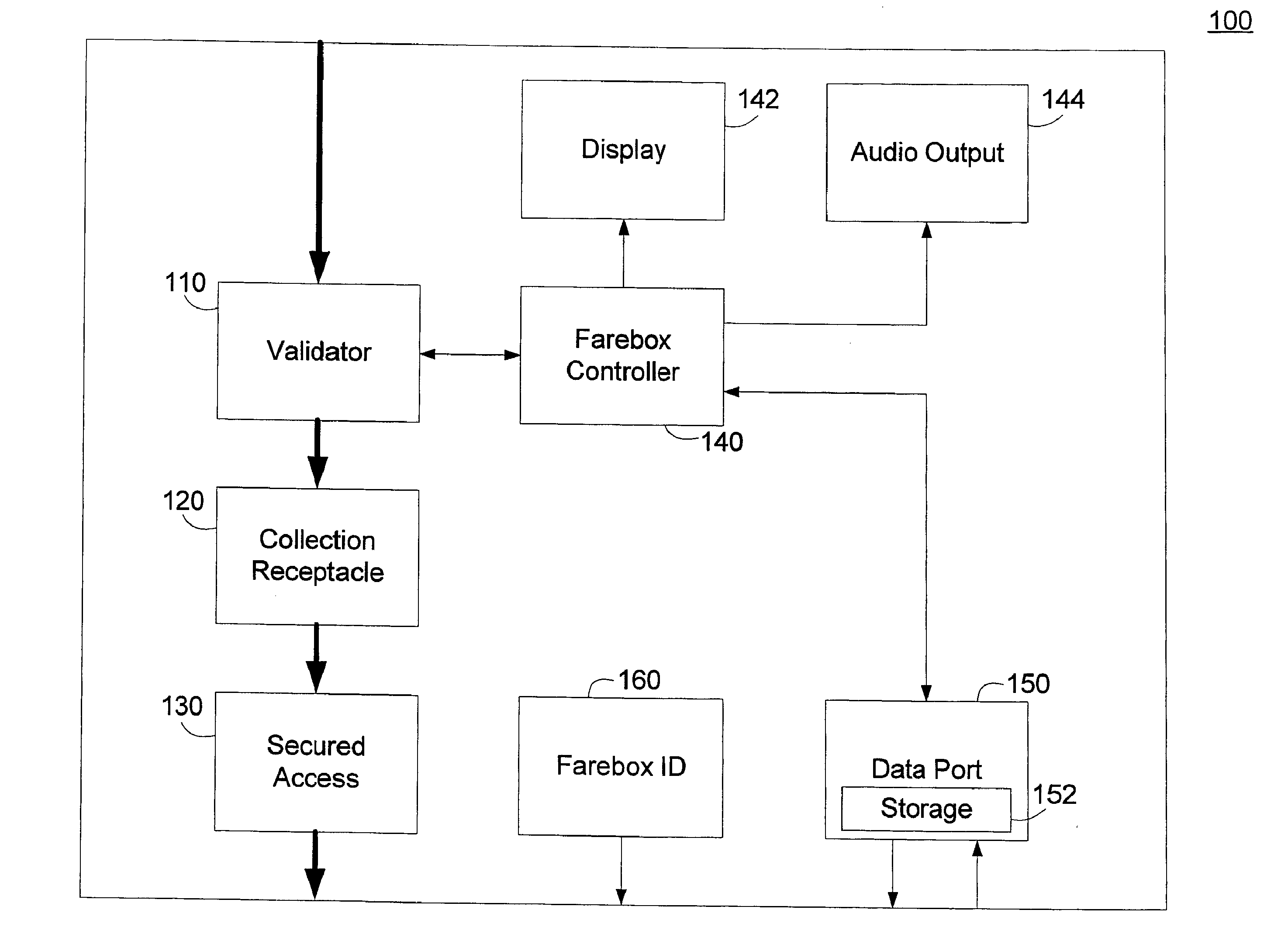
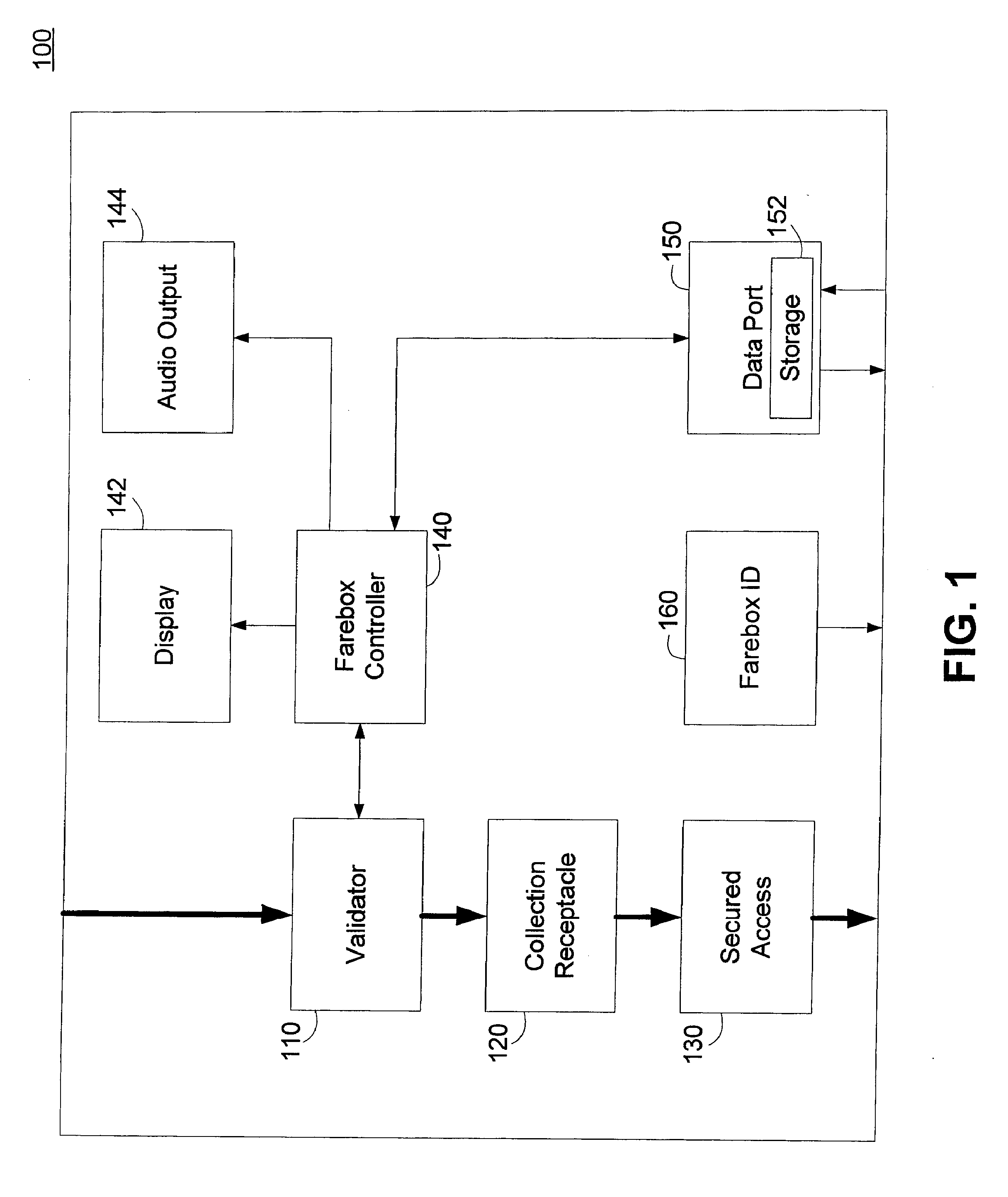
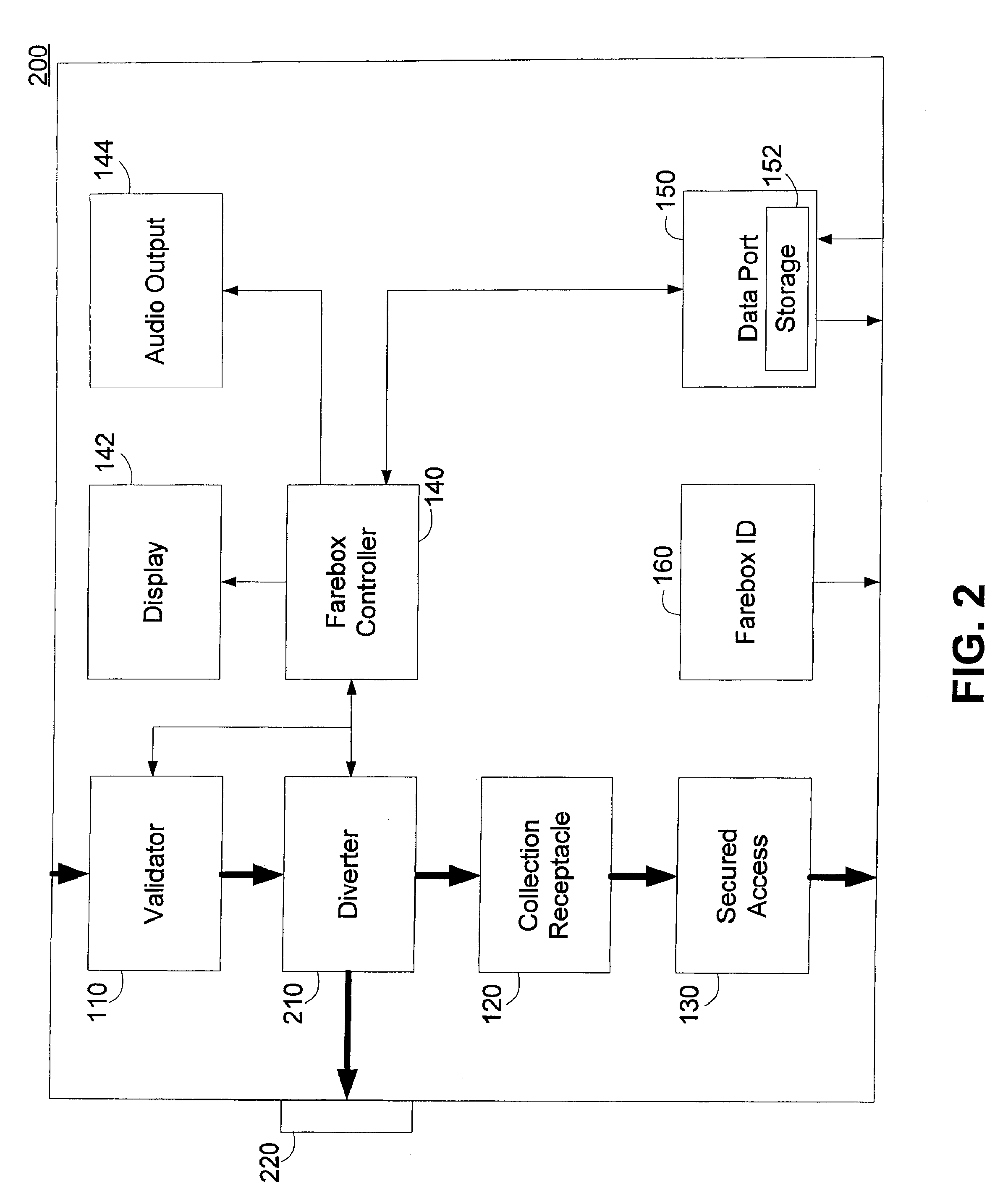
[0026] A low cost removable validating farebox with extremely high reliability is disclosed. In one embodiment the removable farebox can automate coin collection within a fare collection system. The removable farebox can be configured to be installed and removed from a revenue collection point with minimal time and minimal or no tools.

[0027] The removable farebox can be configured to receive coins or tokens inserted into a coin collection slot. The coins can be configured to fall through the slot and be directed to a coin validator. The validator can be configured to validate the value of the coin or token and count the received fare. The received coins can be directed to a secured section of the removable farebox where all received fares are collected.

[0028] The validator can be configured to automatically identify real vs. fake coins, count coins, store a running tally, and present the running tally on a patron display. If the collected fare meets the expected fare, the removabl...


PUM


Abstract

A low cost fare collection system includes a removable farebox having an integral collection box. The farebox can be installed in a temporary installation at a fare collection location for the collection of fares and can be removed to a secure location for emptying and reconciliation. The farebox can include an integral collection box for receiving fares deposited in the farebox. The farebox can be configured such that the collected fares can be emptied only when the farebox is removed from the temporary installation to reduce tampering and theft. A fare validator can be used to verify the amount and value of a fare deposited in the farebox to eliminate human validation of fares. Electronic monitors can collect data relating to fares deposited, total revenue collected, time of fare collection, and other data items that can be retrieved when the farebox is removed and emptied.

Description

CROSS-REFERENCES TO RELATED APPLICATIONS [0001] This application is a divisional of U.S. patent application Ser. No. 11 / 036,203, filed Jan. 14, 2005, which claims the benefit of U.S. Provisional Application No. 60 / 536,821, filed Jan. 14, 2004, entitled “AUTOMATICALLY VALIDATING REMOVABLE FAREBOX AND COLLECTION SYSTEM,” each of which is hereby incorporated by reference herein in its entirety.BACKGROUND OF THE INVENTION [0002] Revenue collection represents an integral part of many service industries. Transportation related services embody a large portion of revenue collection opportunities. For example, transportation services such as trains, buses, taxis, and cars for hire typically collect a fare from passengers that may be a fixed fare or may be determined based on a distance or time. Services such as parking or road access can also be sources of revenue collection, as a fare is typically collected based on access. For example, fees for parking may be collected on the basis of time...

Claims


Application Information

Patent Timeline
Patent Type & Authority Applications(United States)
IPC IPC(8): G06F17/00G07B15/00G07B15/02G07F7/08G07F9/04G07F9/06G07F9/10G07F17/32
CPCG07B15/02G07F9/06G07F9/04G07F7/08
Inventor BRUMFIELD, JEFFREY S.LAPCZYNSKI, DAVID
Owner CUBIC CORP
Learn More