Vehicle air conditioner
a technology for air conditioners and vehicles, applied in vehicle maintenance, vehicle cleaning, transportation and packaging, etc., can solve the problems of deteriorating the mounting performance of vehicles, increasing the temperature variation, and large door operating force, so as to improve the air-conditioning feeling of passengers adjacent to the side windshield, and improve the defogging performance of the side windshield.
- Summary
- Abstract
- Description
- Claims
- Application Information
AI Technical Summary
Benefits of technology
Problems solved by technology
Method used
Image
Examples
first embodiment
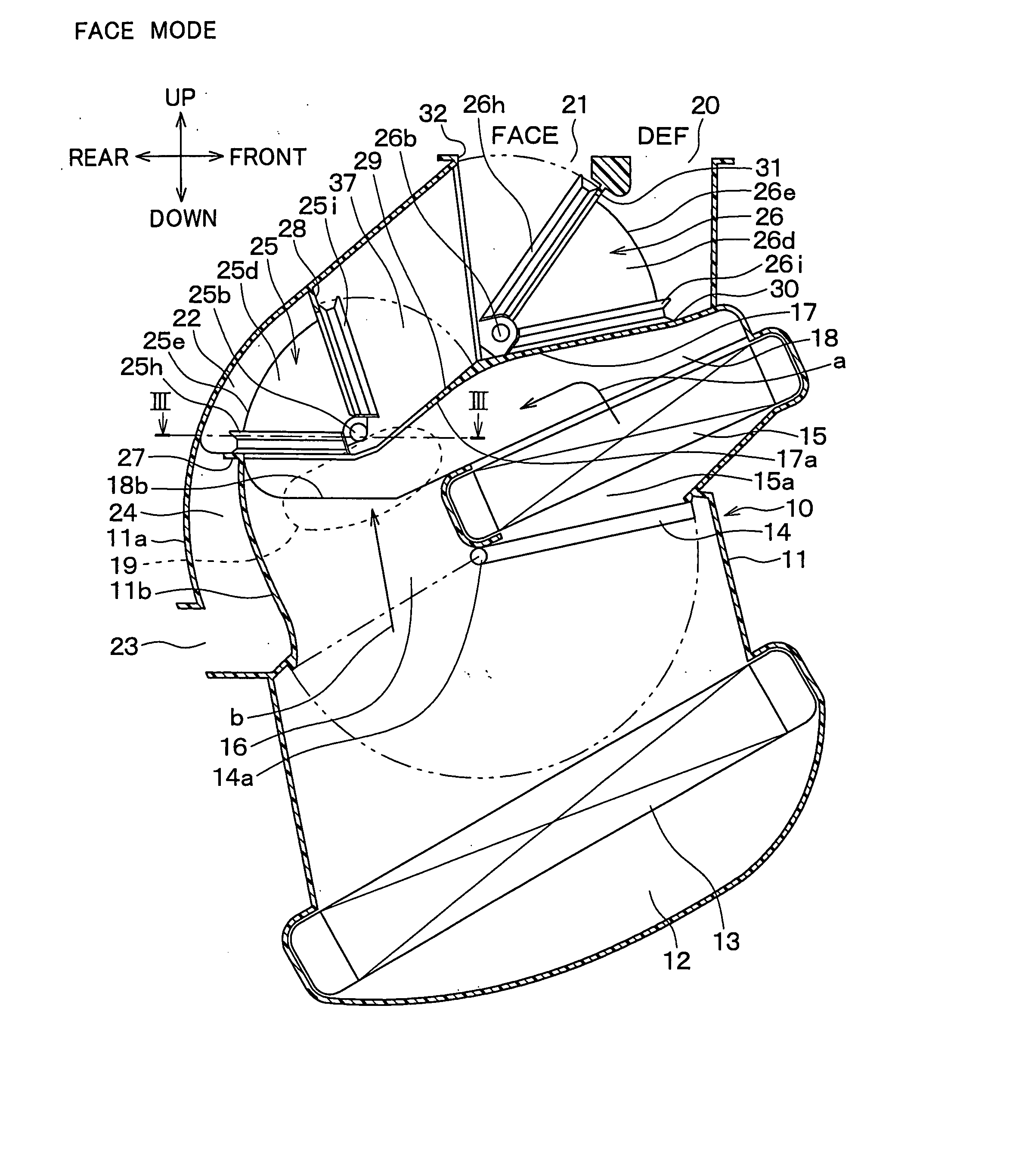
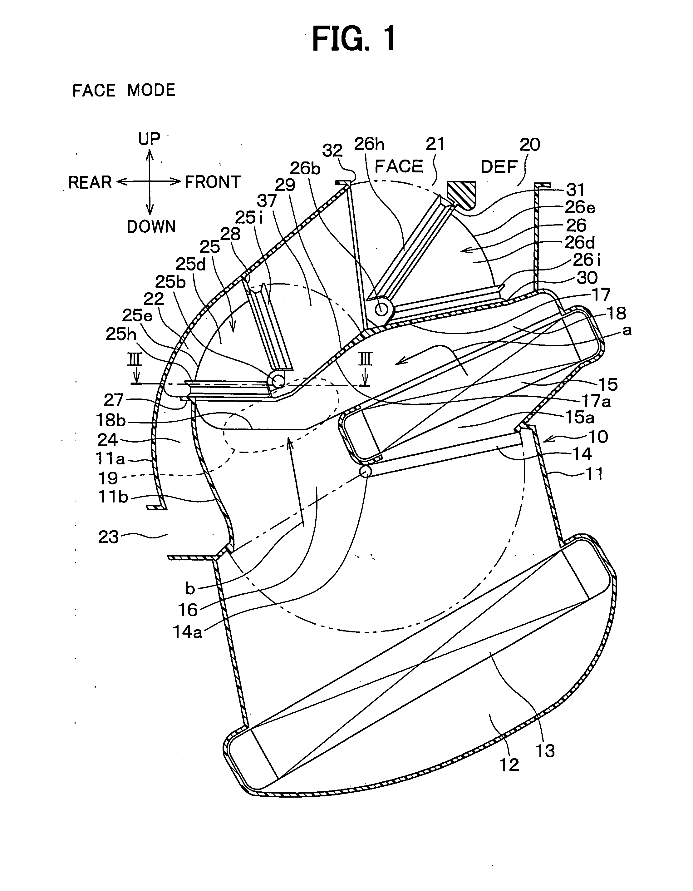
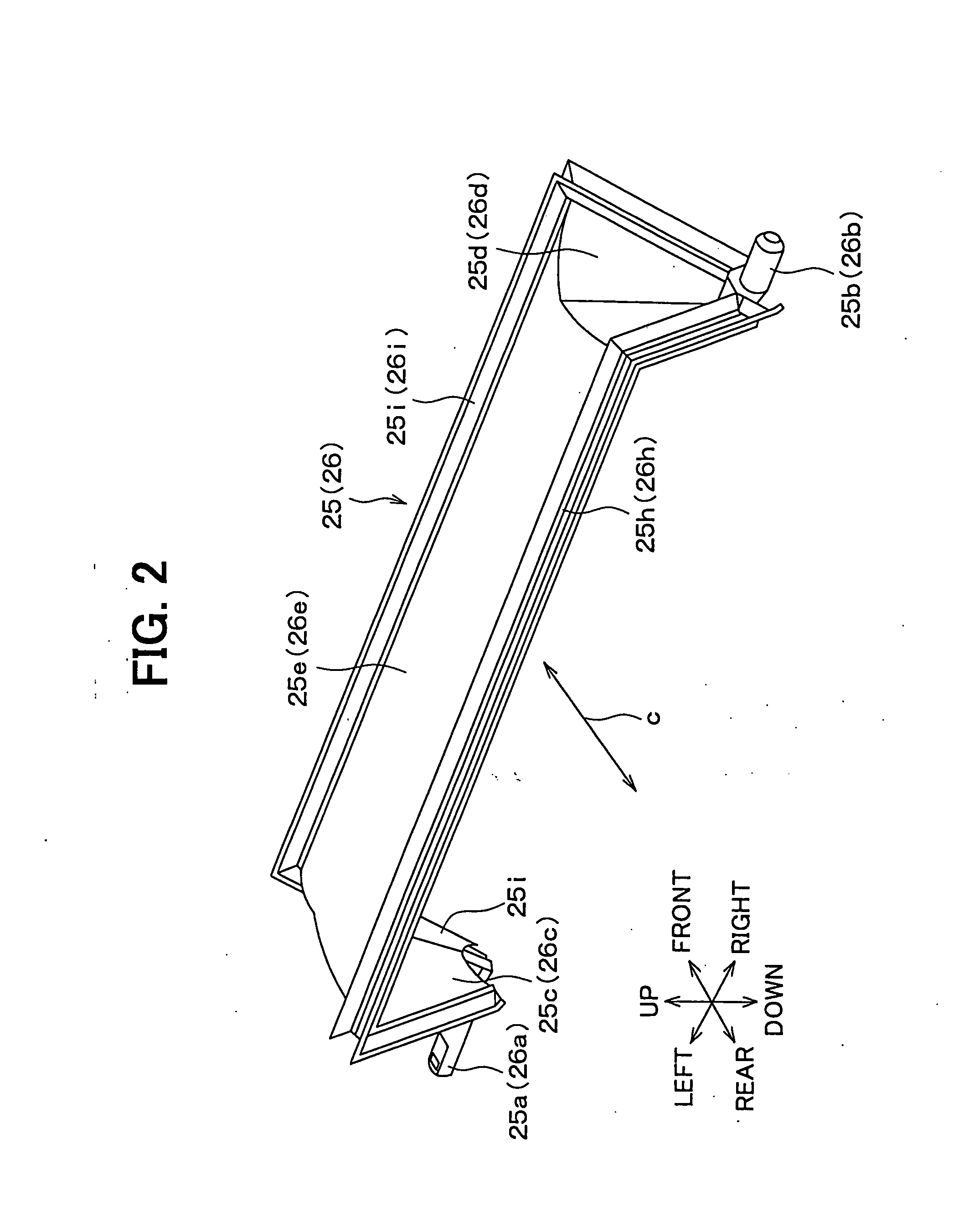
[0042] The first embodiment of the present invention will be now described with reference to FIGS. 1-7.
[0043] An air conditioning unit 10 shown in FIG. 1 is arranged nearly at the center in the width direction (right-left direction) of a vehicle inside an instrument panel (i.e., dashboard) at the front in a passenger compartment. The interior unit of an air conditioner for a vehicle is broadly divided into the above-described air conditioning unit 10 arranged nearly at the center and a blower unit (not shown) arranged in a position offset to a front passenger's seat in the width direction from the center inside the instrument panel.
[0044] The blower unit has an inside / outside air switching box for selectively introducing outside air (i.e., air outside the passenger compartment) and inside air (i.e., air inside the passenger compartment), and a centrifugal blower for blowing air introduced into this inside / outside air switching box. The air blown by this blower unit flows into a lo...
second embodiment
[0113] The second embodiment of the present invention will be now described with reference to FIGS. 8 and 9.
[0114] In the above-described first embodiment, a region where the first rotary door 25 is turned and a region where the second rotary door 26 is turned are set independently from each other. However, in the second embodiment, any one of the first and second rotary doors 25, 26 is arranged in a stacked manner inside the other rotary door. In this manner, the region where the first rotary door 25 is turned partially overlaps the region where the second rotary door 26 is turned.
[0115]FIG. 8 and FIG. 9 show the second embodiment. FIG. 9 is a cross-sectional view taken on the line IX-IX in FIG. 8. A length L1 in an axial direction of the outer peripheral door surface 25e of the first rotary door 25 is made a specified length shorter than a length L2 in the axial direction of the outer peripheral door surface 26e of the first rotary door 26. Thus, the gate-shaped first rotary doo...
third embodiment
[0119] The third embodiment of the present invention will be now described with reference to FIG. 10. The third embodiment is different in the arrangement of the air outlet openings 20, 21, 22 from the first and second embodiments. That is, in the third embodiment, as shown in FIG. 10, the foot openings 22 are arranged at portions near the uppermost portions of the left and right side walls of the case 11 and on the rear side of the vehicle of the defroster opening 20. In addition, the face opening 21 is arranged at a portion adjacent to the air mixing portion 19 of the wall surface on the rear side of the vehicle of the case 11.
[0120] In the air conditioner for a vehicle, an air-outlet mode is usually...selected in the order of (1) face mode→(2) bi-level mode (3) foot mode→(4) foot / defroster mode→(5) defroster mode, relative to the operating direction of the actuator mechanism or the manual operation mechanism of the air-outlet mode door operation mechanism.
[0121] According to th...
PUM
 Abstract
Description
Claims
Application Information
 - R&D
- Intellectual Property
- Life Sciences
- Materials
- Tech Scout
- Unparalleled Data Quality
- Higher Quality Content
- 60% Fewer Hallucinations
Browse by: Latest US Patents, China's latest patents, Technical Efficacy Thesaurus, Application Domain, Technology Topic, Popular Technical Reports.
© 2025 PatSnap. All rights reserved.Legal|Privacy policy|Modern Slavery Act Transparency Statement|Sitemap|About US| Contact US: help@patsnap.com


