
Pulmonary mattress

Active Publication Date: 2007-11-22
HILL ROM SERVICES
View PDF94 Cites 54 Cited by
  • Summary
  • Abstract
  • Description
  • Claims
  • Application Information

AI Technical Summary

Benefits of technology

[0009] In some embodiments, the patient-support apparatus may further comprise a second inflatable structure supported on the first inflatable structure. When both the first and second inflatable structures are present, the first inflatable structure may deflate in response to

Problems solved by technology

When the first inflatable structure is present, articulation of

Method used


Image

  • Pulmonary mattress
  • Pulmonary mattress
  • Pulmonary mattress

Examples


Example

DETAILED DESCRIPTION OF THE DRAWINGS

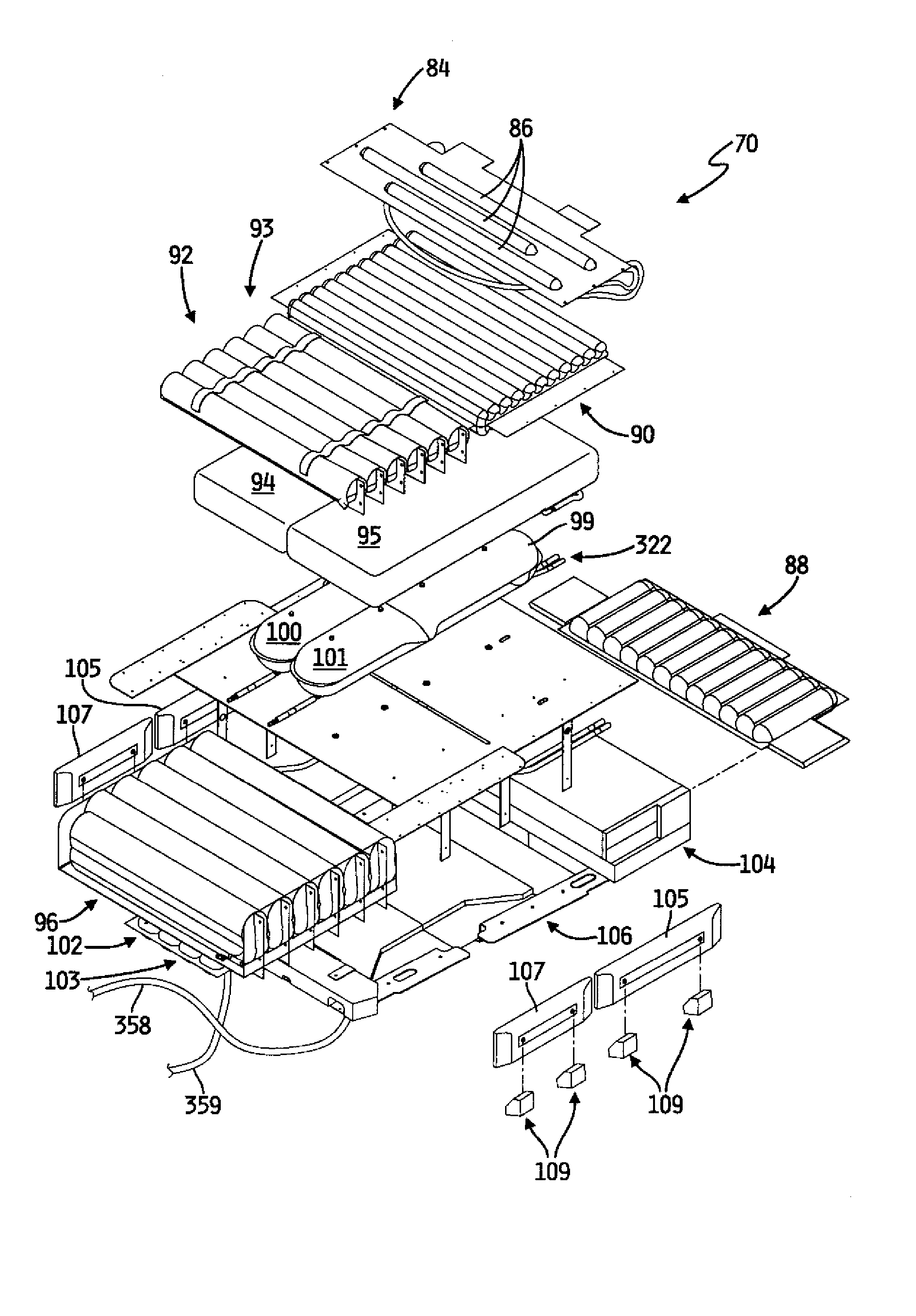
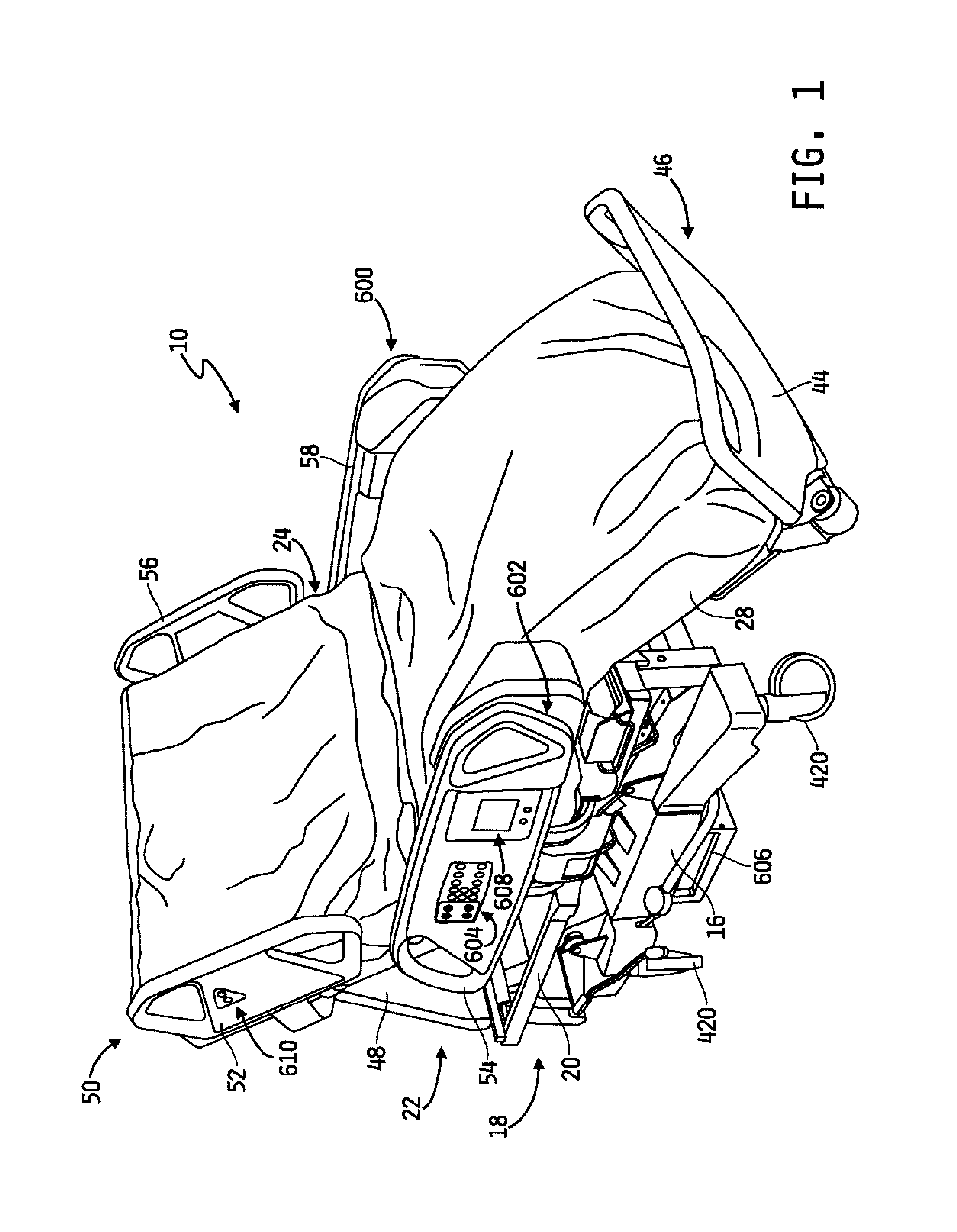
[0050] A patient-support apparatus illustratively embodied as a hospital bed 10 includes a frame 12 (see FIGS. 19A and 19B) and a mattress assembly 14 (see FIG. 16) coupled to the frame. Illustratively, mattress assembly 14 is a patient-support surface integrated with the frame 12 and including foam components and a plurality of inflatable structures which are separately inflatable to provide therapy and support to a patient supported on the mattress assembly 14. It is within the scope of this disclosure for the patient-support apparatus to support patients of up to 1000 pounds or more. To accommodate patients of varied sizes, the patient-support apparatus may have a width of up to 50 inches or more. Thicknesses of inflatable structures such as air cells, bladders, tubes, etc., as discussed herein, may be formed of conventional thicknesses or have a thickness thicker than conventional thicknesses to support bariatric patients up to 1000 pounds (4...


PUM


Abstract

A patient-support apparatus includes a mattress assembly supported on a frame, the mattress assembly including a coverlet configured to provide low-airloss therapy to a patient supported on the patient-support apparatus. The patient-support apparatus is articulable to a number of positions and includes a control network which is responsive to movement of portions of the frame to alter operational parameters of the frame and mattress assembly.

Description

[0001] This application claims the benefit, under 35 U.S.C. § 119(e), of U.S. Provisional Patent Application Ser. No. 60 / 799,435 filed May 9, 2006 which is hereby incorporated by reference herein in its entirety.BACKGROUND OF THE INVENTION [0002] The present disclosure is related to a patient-support apparatus. More specifically, the present disclosure is related to a patient-support apparatus configured to support a patient with pulmonary complications. [0003] Bariatrics is the area of medicine related to the management of obesity and diseases and clinical conditions related to obesity. In care environments, such as hospitals, for example, obese patients present special issues related to their care. For example, standard patient handling equipment is not typically sized or rated to support obese patients. In addition, patient therapy devices are not typically sized to fit obese patients. Those patient therapy devices which are sized to fit obese patients may not be configured to pr...

Claims


Application Information

Patent Timeline
IPC IPC(8): A61G7/015A61G7/057A47C27/10
CPCA61G7/001A61G7/015A61G2203/42A61G2007/05784A61G7/005A61G7/05776A61G2203/10A61G7/05784A61G7/05792
Inventor O'KEEFE, CHRISTOPHER R.WILSON, BRADLEY T.RICHARDS, SANDY M.MEYER, ERIC R.
Owner HILL ROM SERVICES
Learn More