Audiometer receiver and audiometer
- Summary
- Abstract
- Description
- Claims
- Application Information
AI Technical Summary
Benefits of technology
Problems solved by technology
Method used
Image
Examples
Embodiment Construction
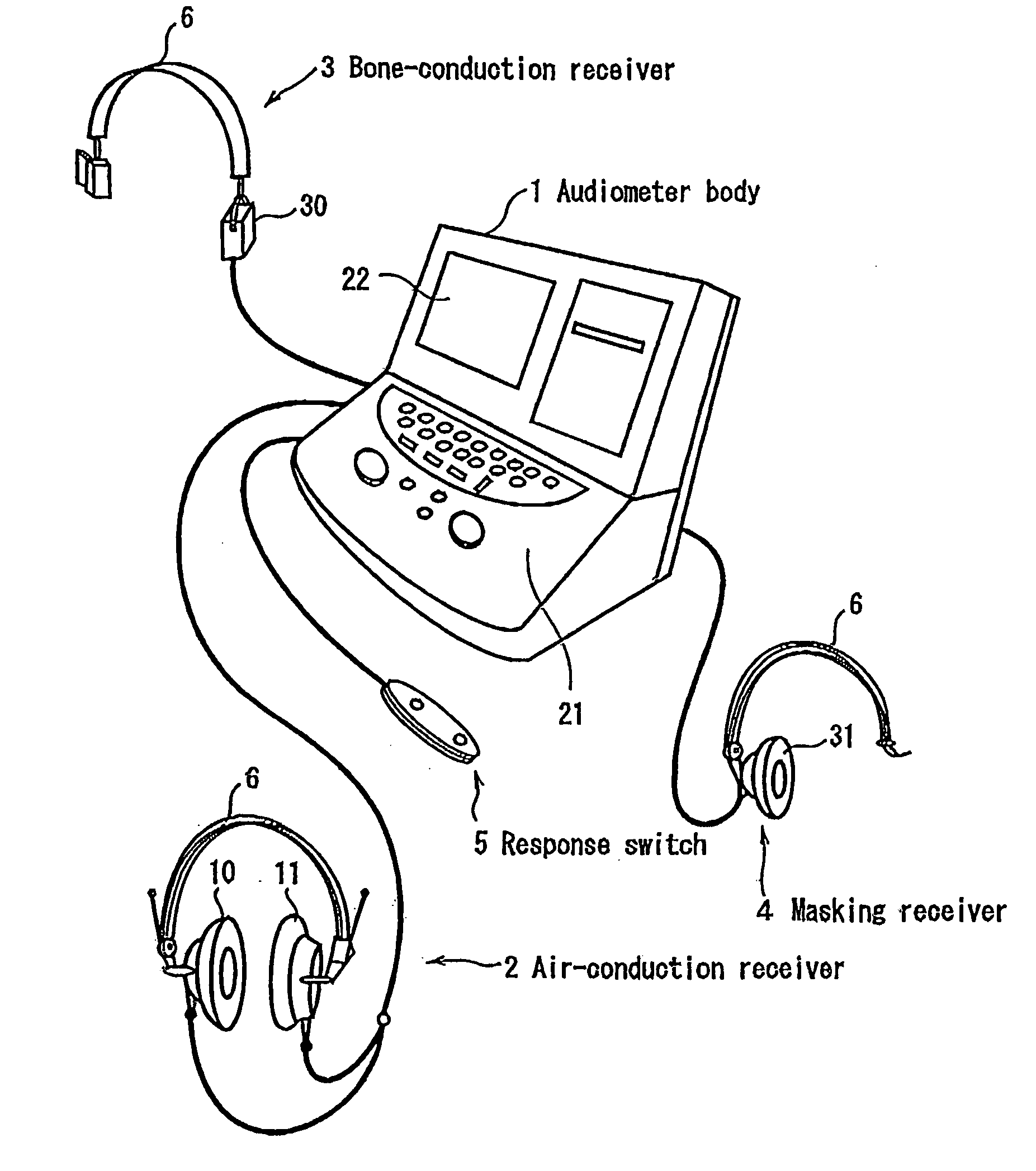
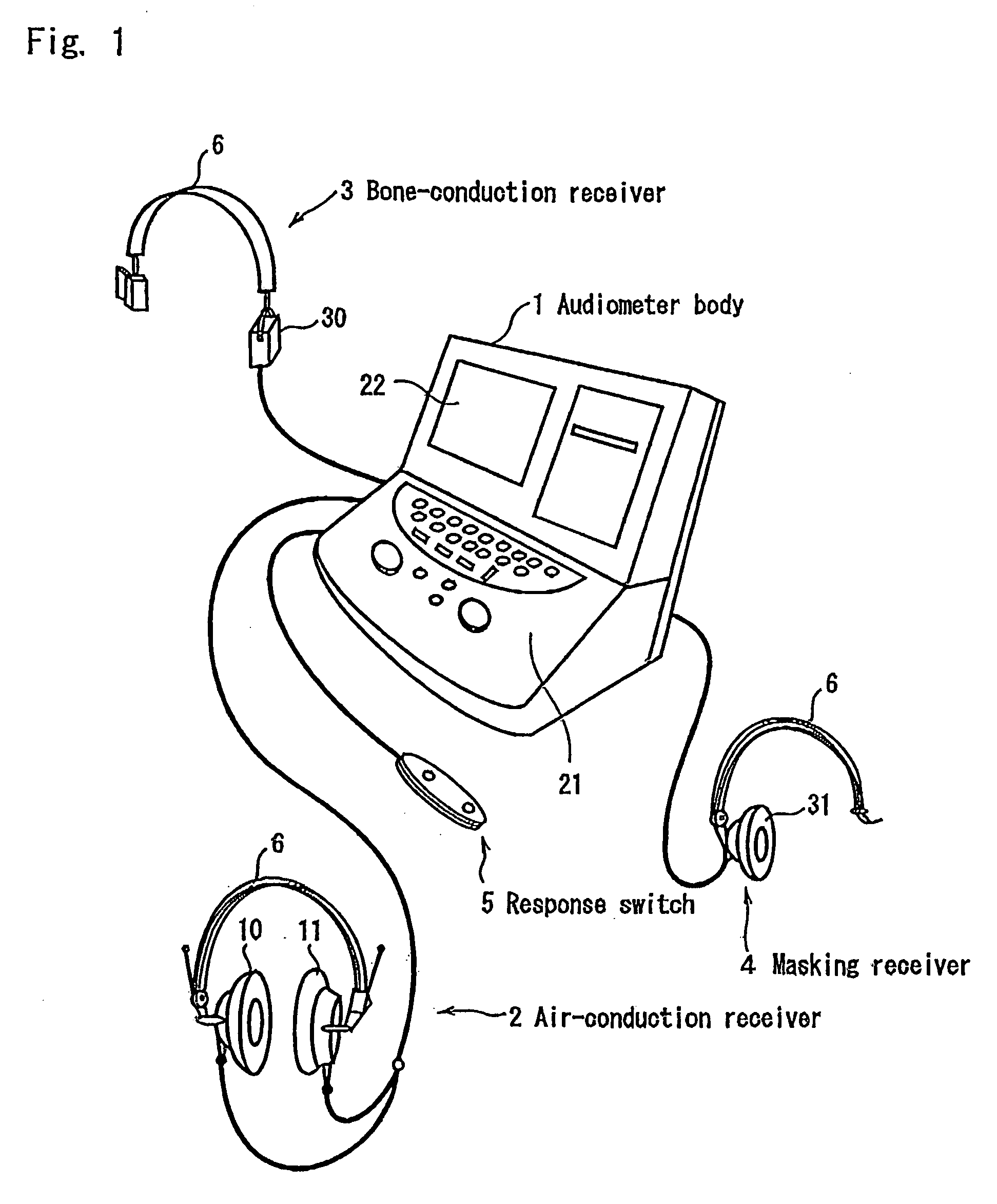
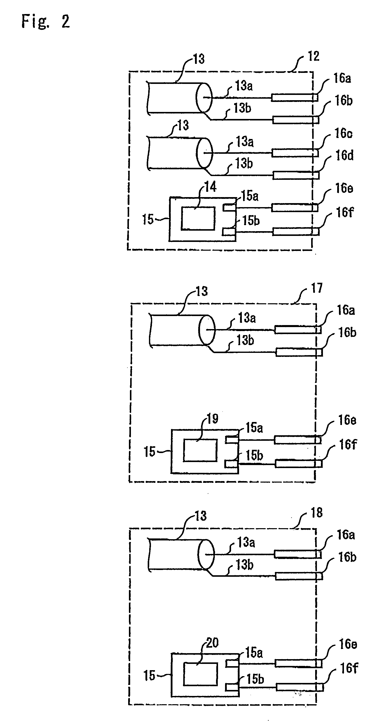
[0018]A preferred embodiment of the present invention will now be described with reference to the accompanying drawings. FIG. 1 is a schematic perspective view of an audiometer according to the present invention, FIG. 2 is a schematic diagram of a connector of an audiometer receiver according to the present invention, and FIG. 3 is a block diagram of the audiometer.
[0019]As shown in FIG. 1, an audiometer according to the present invention consists of an audiometer body 1, an air-conduction receiver 2, a bone-conduction receiver 3, a masking receiver 4, and a response switch S. Each receiver 2, 3 and 4 is connected to a headband 6 so that a test subject can wear it during an audiometric test.
[0020]The air conduction receiver 2 is composed, as shown in FIGS. 1 and 2, of a right receiver 10, a left receiver 11, a connector 12 for connecting to the audiometer body 1, and two coaxial cables 13 for connecting the right receiver 10 and the left receiver 11 to the connector 12, respectively...
PUM
 Abstract
Description
Claims
Application Information
 - R&D
- Intellectual Property
- Life Sciences
- Materials
- Tech Scout
- Unparalleled Data Quality
- Higher Quality Content
- 60% Fewer Hallucinations
Browse by: Latest US Patents, China's latest patents, Technical Efficacy Thesaurus, Application Domain, Technology Topic, Popular Technical Reports.
© 2025 PatSnap. All rights reserved.Legal|Privacy policy|Modern Slavery Act Transparency Statement|Sitemap|About US| Contact US: help@patsnap.com


