
Method of interpreting well data

a well data and data technology, applied in the field of well data interpretation, can solve the problems of complex structure, difficult to predict hydrocarbon production efficiency, etc., and achieve the effect of reasonable predictability

Active Publication Date: 2007-11-08
SCHLUMBERGER TECH CORP
View PDF9 Cites 16 Cited by
  • Summary
  • Abstract
  • Description
  • Claims
  • Application Information

AI Technical Summary

Benefits of technology

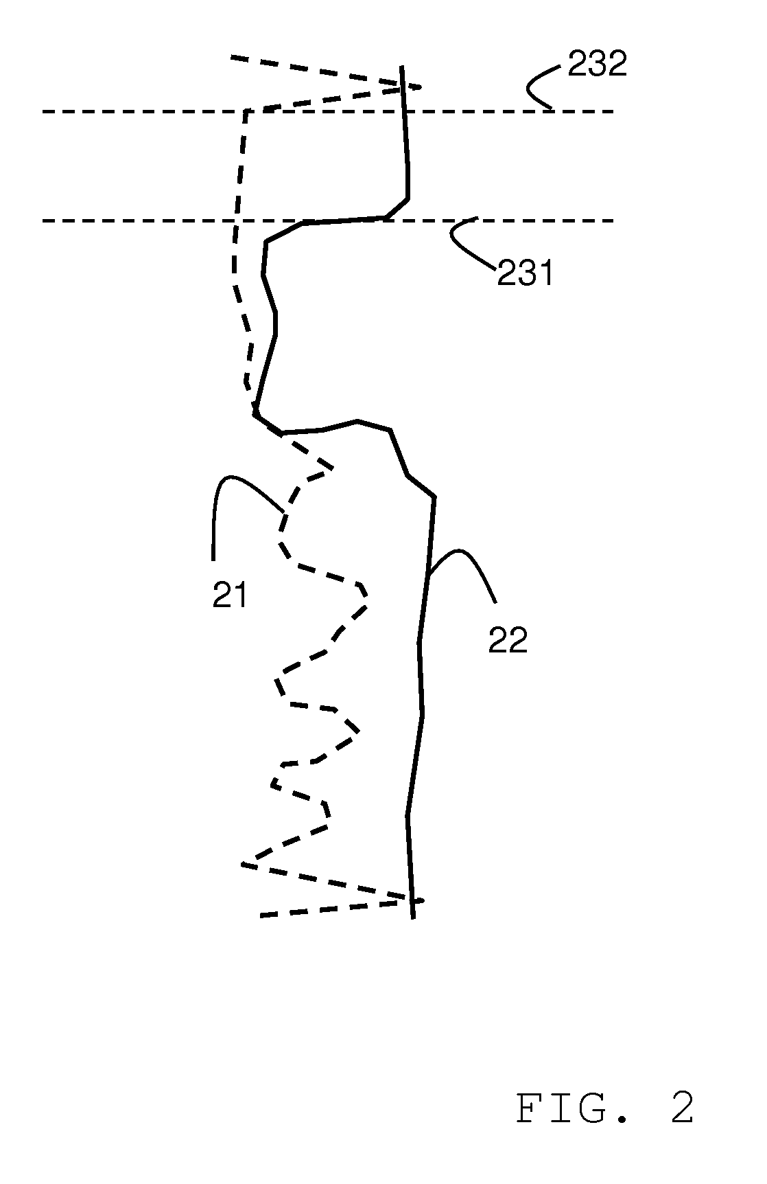
[0027] According to another aspect of the invention, there is provided a method that allows the distinction of a mainly diagenetically produced surface in geological strata from that formed from mainly depositional processes within carbonate rocks, but also within any other sedimentary rock including siliclastic, evaporite, or organic. The divergence of any wireline signature (including Density; Resistivity; Neutron; ECS etc.) from one that is known by interpretation from core material (or other geological data source) to be of primarily depositional origin (including Gamma; ECS etc.) is deduced to mark a diagenetic surface and / or layer rather than a depositional one. This enables an understanding of the processes responsible for the demarcation of reservoir or dense zones on the basis of both depositional and diagenetic processes, and also allows for more accurate timeline correlation to be performed using wireline data.
[0033] Prior log interpretation methods do not often allow any differentiation to be made between those components of the signatures derived from the original depositional lithology, and those from subsequent diagenetic overprinting. Such a differentiation is important because the same depositional lithology may be found with distinct and differing diagenetic overprints in different parts of a reservoir or between reservoirs of the same formation, so apparently reducing the utility of well logs for the valid extrapolation of many reservoir characteristics into the inter-well volume. Such differentiation will therefore enable more accurate construction of 3D geological models because depositional lithologies can be interpolated with a reasonable predictability and hence accuracy, and diagenetic overprints can be simulated separately with either deterministic, simulated models, or by geostatistical methods.

Problems solved by technology

As a result, the pore space in sandstones is mainly intergranular and its complexity depends on the degree of sorting.
These distributions result in wide permeability variations for the same total porosity, making it difficult to predict for example the production efficiency for hydrocarbon.

Method used


Image

  • Method of interpreting well data
  • Method of interpreting well data
  • Method of interpreting well data

Examples


Embodiment Construction

[0040] Each stage of the invention is now described in more detail.

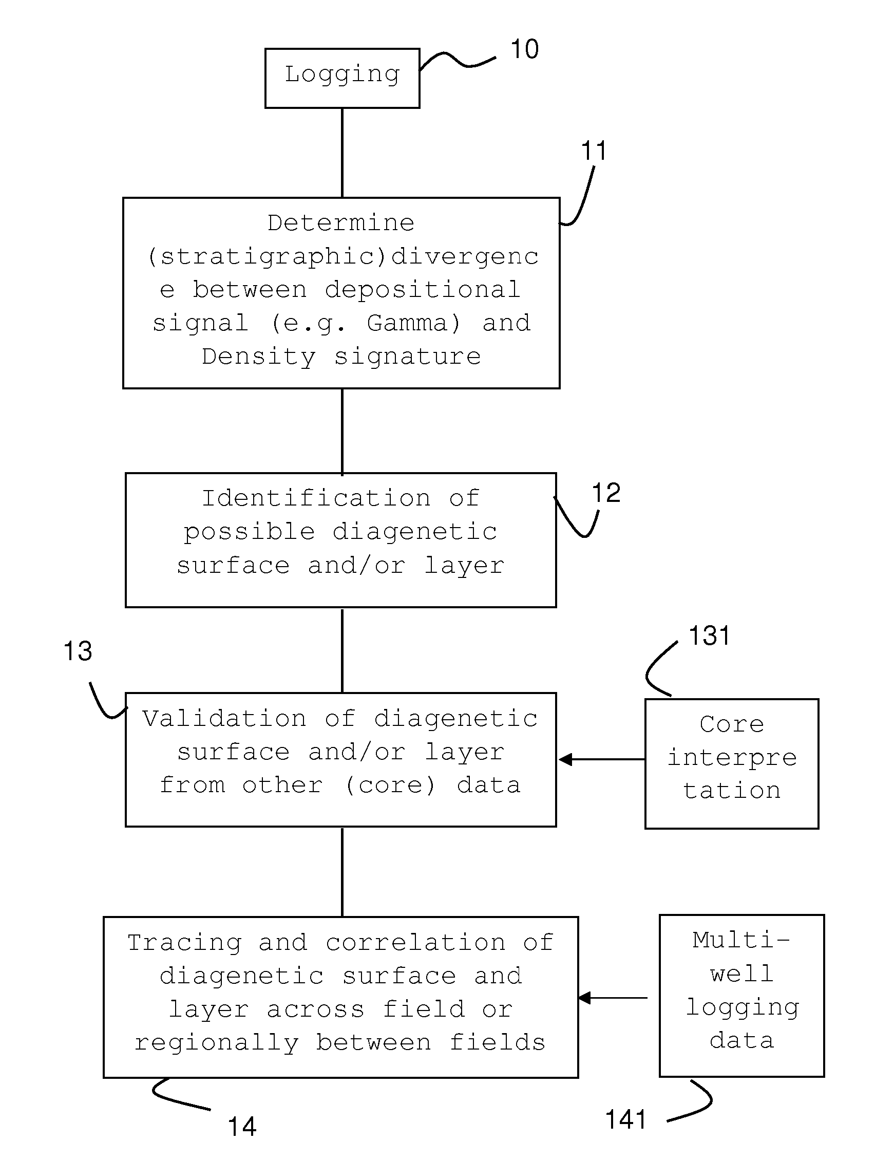
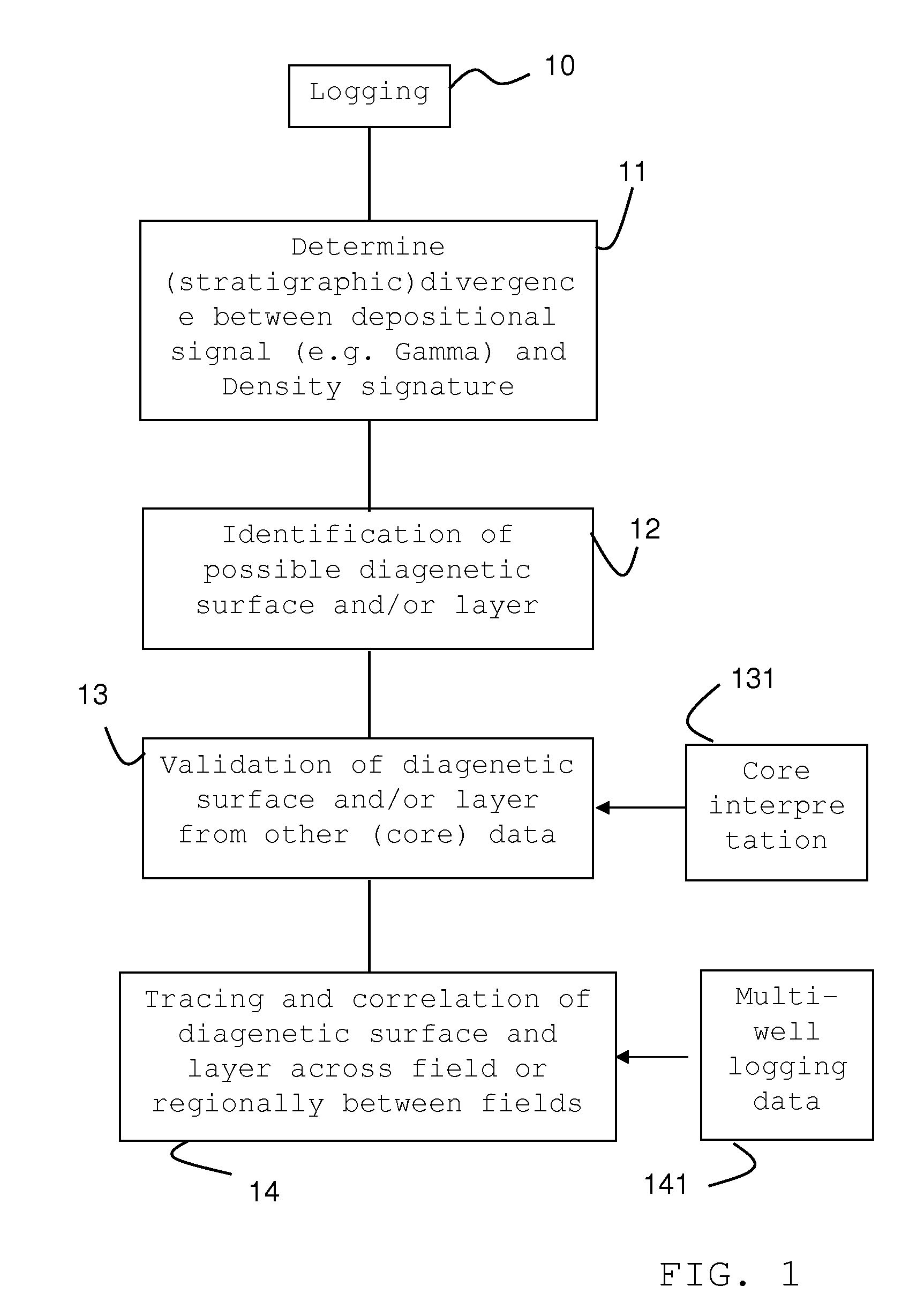
[0041] After a logging operation which may be performed using known wireline tools or logging-while-drilling (LWD) tools (step 10 of FIG. 1), a plurality of log signatures of the well are recorded. The logging and following interpretation according to the invention can be conducted on vertical, horizontal, or deviated wells. For the present example a gamma ray and a density log are measured and recorded.

[0042] The invention includes the step 11 of detecting any stratigraphic divergence between any given log signal known to be influenced mainly by depositional lithology like gamma ray logs and logging signal which can be influenced by diagenetic processes in the formation like the density logs.

[0043] In FIG. 2 there are shown a set of two wireline signatures in a deviated well through the Thamama Formation in the United Arabian Emirates.: The gamma ray log signature 21 is shown as dashed line and the density log 22...


PUM


Abstract

The present invention provides method for detecting the possible presence of surfaces layers of diagenetic origin by establishing divergence between well signatures such as logs, particularly for use in predominantly carbonate reservoirs.

Description

[0001] The subject matter of the present invention relates to a method of interpreting data derived from one or more wells, particularly log data derived from one or more wells in one or more logging operations. Even more specifically, the method relates to a method of identifying diagenetic surfaces in reservoirs. BACKGROUND OF THE INVENTION [0002] Today's hydrocarbon production stems to a large part from two types of reservoirs. One type is predominantly composed of siliciclastic rocks or sediments. The other reservoirs are classified as carbonate reservoirs. As the latter reservoir type is at the focus of the present invention, it is worth noting that the interpretation of log data derived from well measurement and the accuracy of the interpretation differ significantly depending on the type of reservoir. These differences emerge as a result of the internal structure of the two classes of deposits. [0003] Siliciclastic sediments, such as sandstones and shale, develop through the ...

Claims


Application Information

Patent Timeline
IPC IPC(8): G06F19/00G01V1/40
CPCG01V5/12G01V2210/6167G01V2210/6163G01V11/00
Inventor WOOD, RACHEL
Owner SCHLUMBERGER TECH CORP
Learn More