
Cavitation generating system

a generating system and cavitation technology, applied in the direction of transportation and packaging, separation of dispersed particles, separation of separation processes, etc., can solve the problem that the design of the bubble generating system is still not satisfactory in function

Inactive Publication Date: 2007-11-08
CHUANG SHUO WEI
View PDF5 Cites 39 Cited by
  • Summary
  • Abstract
  • Description
  • Claims
  • Application Information

AI Technical Summary

Benefits of technology

[0007] By regulating the amount of air intake and the slit of the reduction value, a cavitation-like condition is generated. The r...

Problems solved by technology

This design of bubble generating system is still not satisfactory in function.

Method used


Image

  • Cavitation generating system
  • Cavitation generating system
  • Cavitation generating system

Examples


Embodiment Construction

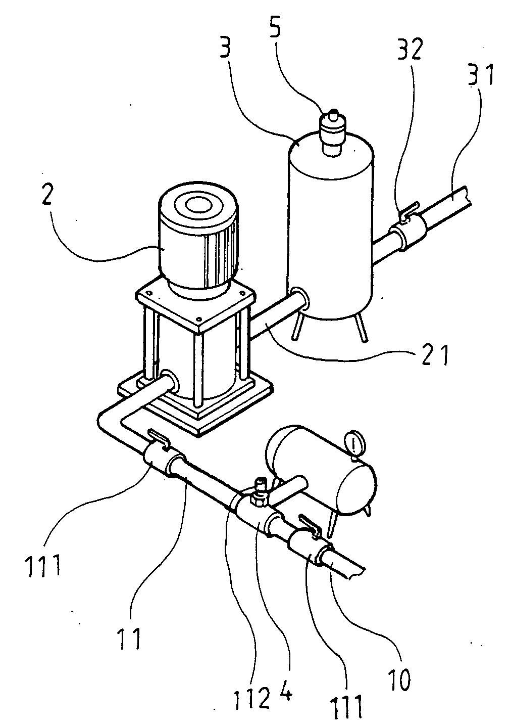
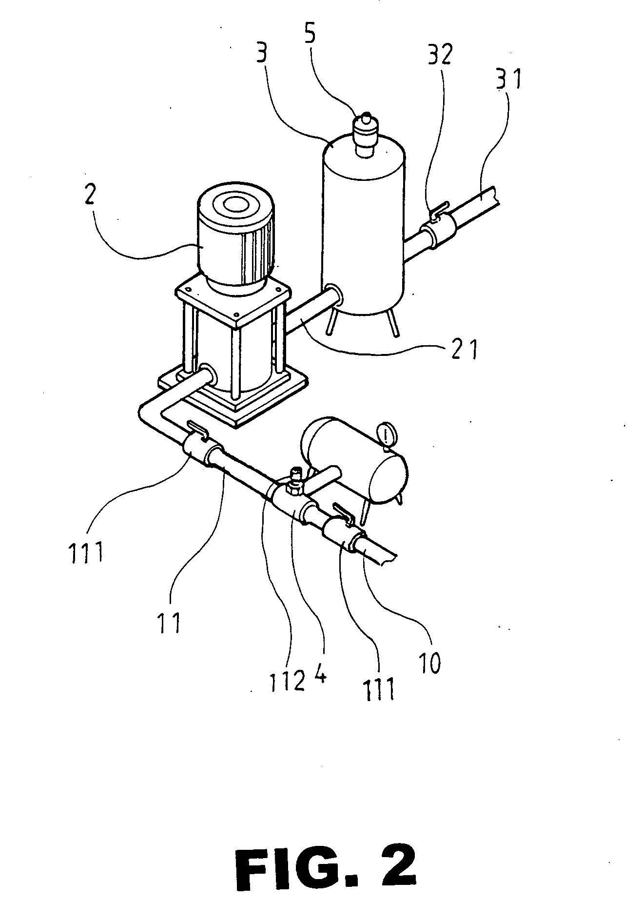
[0014] Referring to FIGS. 2˜5, a cavitation-like generating system in accordance with the present invention is shown comprising an air compressor 1, a pump 2, an accumulation tank 3, a reduction value 32 and a venturi tube 4. The air compressor 1 and the venturi tube 4 are connected in parallel between a water inlet pipe 10 and a first water delivery pipe 11. The first water delivery pipe 11 has one end connected to the air compressor 1 and the venturi tube 4 and the other end connected to the input side of the pump 2. Further, two control valve 111 are placed before and after venturi tube. A gas regulator 112 is provided at venturi tube. The pump 2 has the output side thereof connected to the accumulation tank 3 through a second water delivery pipe 21. The accumulation tank 3 is provided with a relief valve 5 at the top, having a water outlet pipe 31 for water output. The water outlet pipe 31 is provided with a reduction valve 32.

[0015] Referring to FIG. 4 and FIGS. 2 and 3 again,...


PUM

PropertyMeasurementUnit
Pressureaaaaaaaaaa

Abstract

A cavitation-like generating system includes a venturi tube, a pump for pumping water through the venturi tube, an air compressor for providing a compressed gas into the venturi tube to mix with water being pumped into the venturi tube, an accumulation tank for buffering the flow of air-water mixture coming out of the pump for output through a water outlet pipe, and a reduction valve for reducing the pressure of the output flow of air-water mixture through the water outlet pipe.

Description

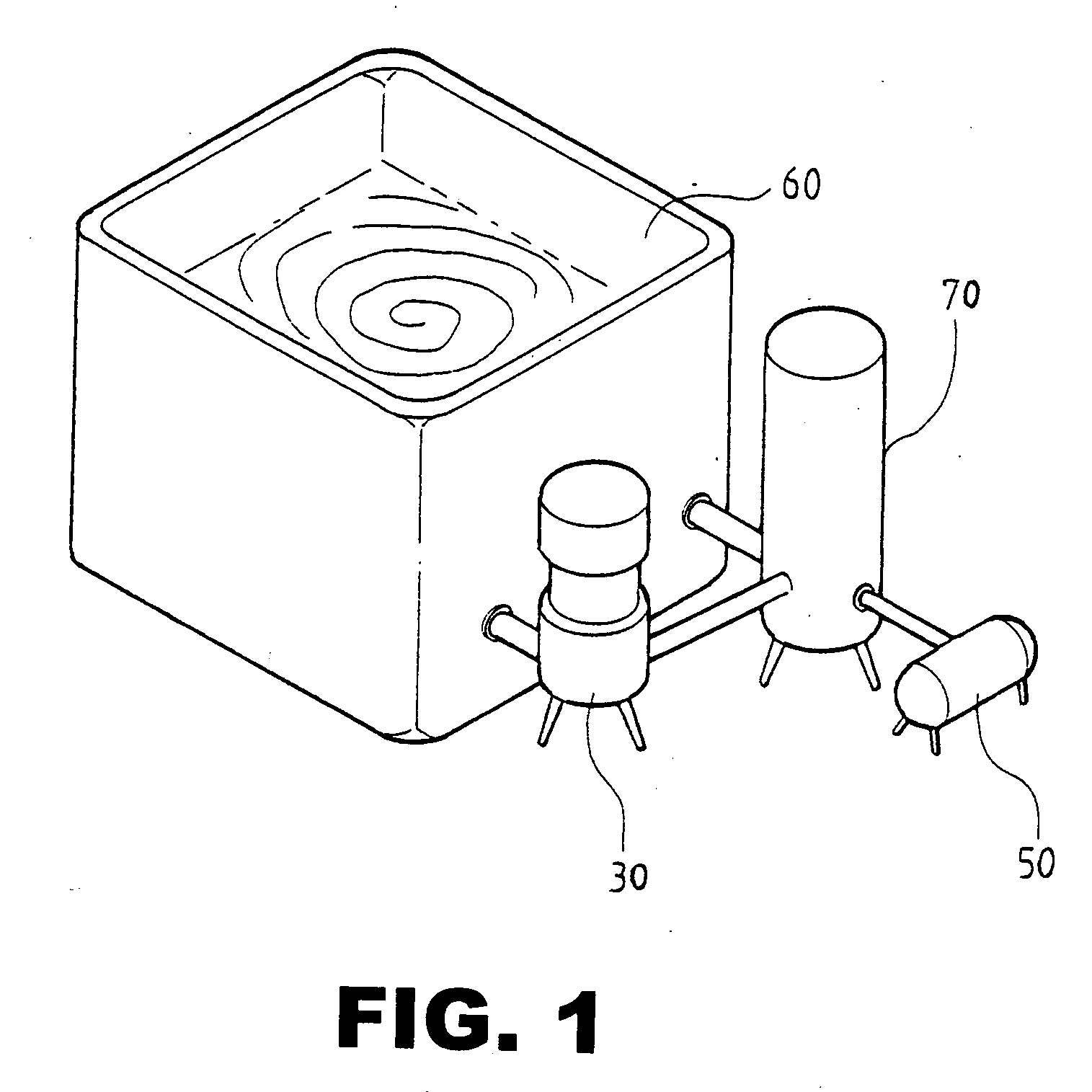
BACKGROUND OF THE INVENTION [0001] 1. Field of the Invention [0002] The present invention is a device which air is introduced before pump to create a cavitation-like condition where water-gas is well mixed. It includes a venturi-tube and / or an air compressor, a pump, an accumulation tank, and a reduction valve. The venturi tube and / or air compressor is connected to the pump, the later is connected to the accumulation tank with the reduction valve. And by regulating the air in-take and the reduction valve, a cavitation-like condition is produced. Because of the high speed of the pump, the pressure so created forces a greater amount of air to dissolve in water and greater amount of micro bubbles, or even much smaller in size are produced. The present invention can be used in cleaning, sterilization, floatation, fermentation, irrigation, aquaculture, and other water-treatment industries. [0003] 2. Description of the Related Art [0004] Various mechanical and electronic bubble generating...

Claims


Application Information

Patent Timeline
IPC IPC(8): B01F3/04
CPCB01F3/0446B01F5/12B01F5/0415B01F23/232B01F25/3121B01F25/60B01F23/2326
Inventor CHUANG, SHUO WEI
Owner CHUANG SHUO WEI
Learn More