Dental wedge

a technology of teeth and wedges, applied in the field of teeth wedges, can solve problems such as punctures on soft tissues

Active Publication Date: 2007-11-01
DENTSPLY SIRONA INC
View PDF14 Cites 21 Cited by
  • Summary
  • Abstract
  • Description
  • Claims
  • Application Information

AI Technical Summary

Benefits of technology

[0008] It is therefore an object of the present invention to provide a wedge for securing dental matrices which is an improvement on the prior art systems and devices or which will at least provide the industry with a useful choice.

Problems solved by technology

In the prior art wedges are not flexible or appropriately shaped and often cause punctures to the soft tissues and so are traumatic.

Method used


Image

  • Dental wedge
  • Dental wedge
  • Dental wedge

Examples


Embodiment Construction

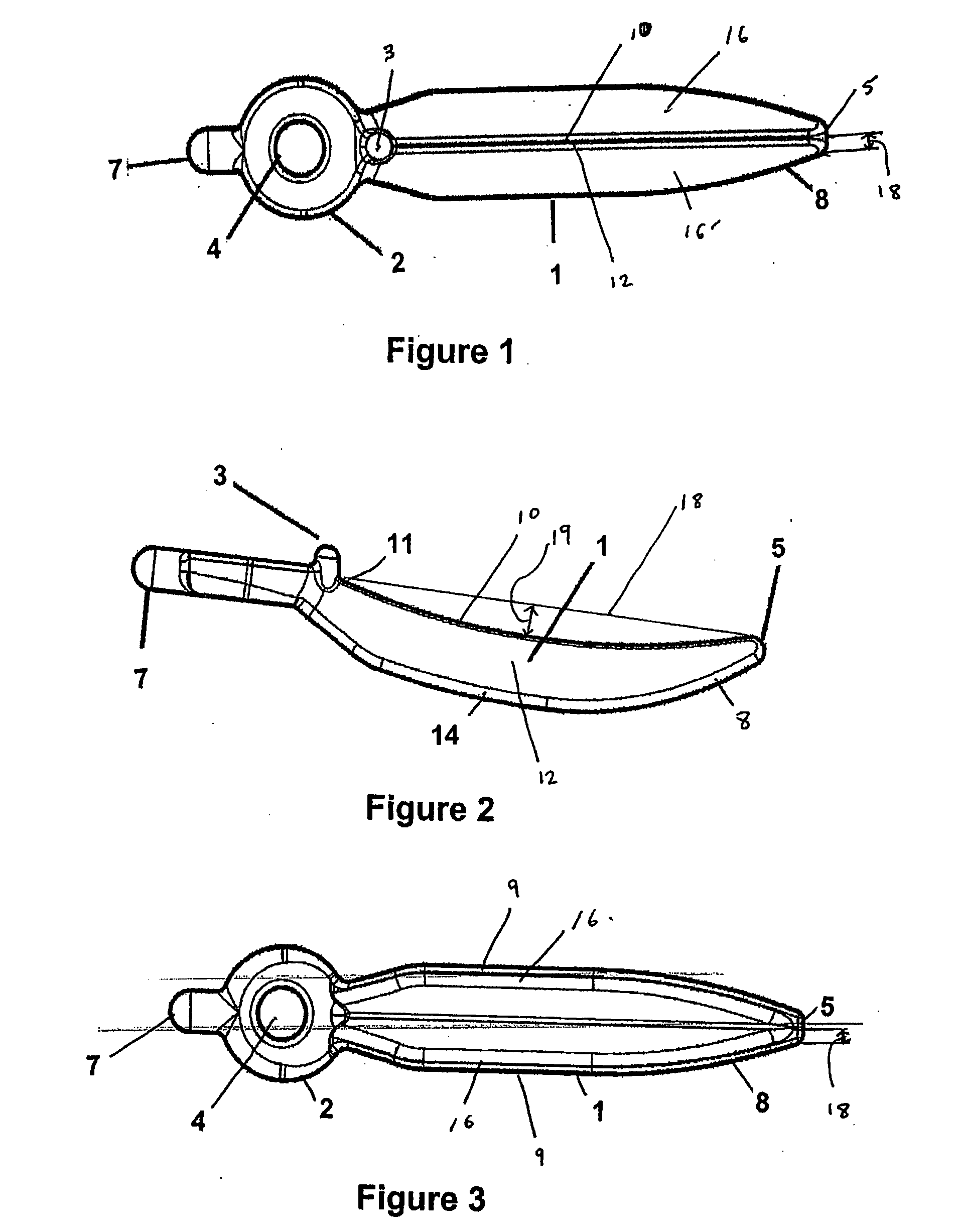
[0072] Referring to FIG. 1 the wedge comprises a one piece member of semi-hard or hard plastic or thermoplastic and has three main parts, a body section 1, a tapered end section 8 and a handle section 2. The wedge has a ridge 10 and two sides 16 and 16′ converging towards the ridge. The ridge 10 runs along the top of the body section 1 and tapered end 8.

[0073] Referring to FIG. 2 the body section 1 when viewed from the side has a curved profile. The ridge 10 of the body section 1 rises from the centre 12 of the body section 1 to the handle end 11 of the body section 1 and at the opposite end to the tapered end section 8

[0074] The tip 5 of the tapered end section 8 is blunt to help prevent damage when the wedge is inserted between teeth. The leading end radius 18 of the tip 5 of the tapered end 8 is greater than 0.2 mm, with the wedge tapering out, so that it is at least 1.3 mm wide 3 mm from the tip 5.

[0075] The wedge between the tip 5 and adjacent the handle 11 is between 10 mm a...


PUM


Abstract

A dental wedge for use in the inter-proximal space between adjacent teeth is described. The wedge comprises a taper section ending at a tip, and a body section extending to the tapering section at one end. The body section has an inverted V-shaped cross-section, flexing of the sides of the V-shape allows the wedge to adapt to various contours of the inter-proximal space. The mid-portion of the body section is narrower than at least a portion of the wedge either end of the mid-portion.

Description

FIELD OF THE INVENTION [0001] The present invention relates to an apparatus for use with dental matrixes in the placement of dental fillings. SUMMARY OF THE PRIOR ART [0002] To enable the dental professional to place composite fillings, matrixes are used. A matrix is a device which wraps around the tooth and acts as a mould to contain composite resins before they are cured. Matrices are generally formed of plastic or stainless steel and are either circumferential or sectional. Sectional matrices fit only in one proximal area of the tooth while circumferential matrix bands fit around the entire circumference of the tooth. Matrixes are secured in place by the use of wedges and / or clamps. The prior art wedges are generally made of wood or plastic and are placed between the matrix and an adjacent tooth. Wedges are used to hold the matrix against the tooth being filled and to temporarily separate the tooth being filled and the adjacent tooth. In the prior art wedges are not flexible or a...

Claims


Application Information

Patent Timeline
Patent Type & Authority Applications(United States)
IPC IPC(8): A61C7/00
CPCA61C5/127A61C5/88
Inventor MCDONALD
Owner DENTSPLY SIRONA INC
Why Eureka
Try Eureka