Flow control valve

a flow control and valve body technology, applied in valve arrangements, engine components, spray nozzles, etc., can solve problems such as complex structur

Inactive Publication Date: 2007-10-11
NANKAI
View PDF7 Cites 15 Cited by
  • Summary
  • Abstract
  • Description
  • Claims
  • Application Information

AI Technical Summary

Benefits of technology

[0017] The invention further resides in a pop-up sprinkler for irrigation comprising a cylindrical water passage, a riser that is vertically mov...

Problems solved by technology

The present inventor considers that the pressure regulators proposed in the above-mentioned United States Patents has problems in their practical uses in that the structure is complicated and the regulator needs to form an aperture for sensing the atmospheric pressure surrounding the regulator assembly.

Method used


Image

  • Flow control valve
  • Flow control valve
  • Flow control valve

Examples


Embodiment Construction

[0028] The present invention is further described by referring to the figures given in the attached drawings.

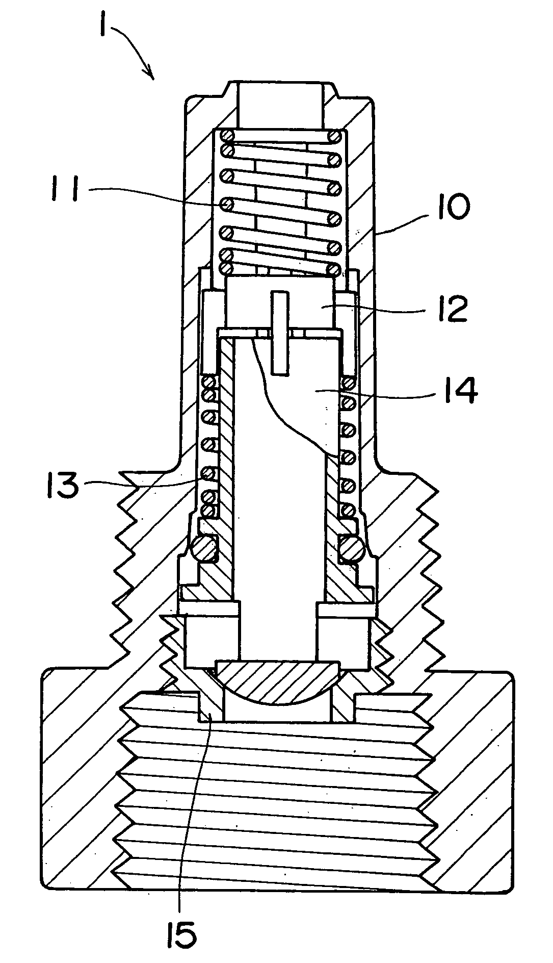
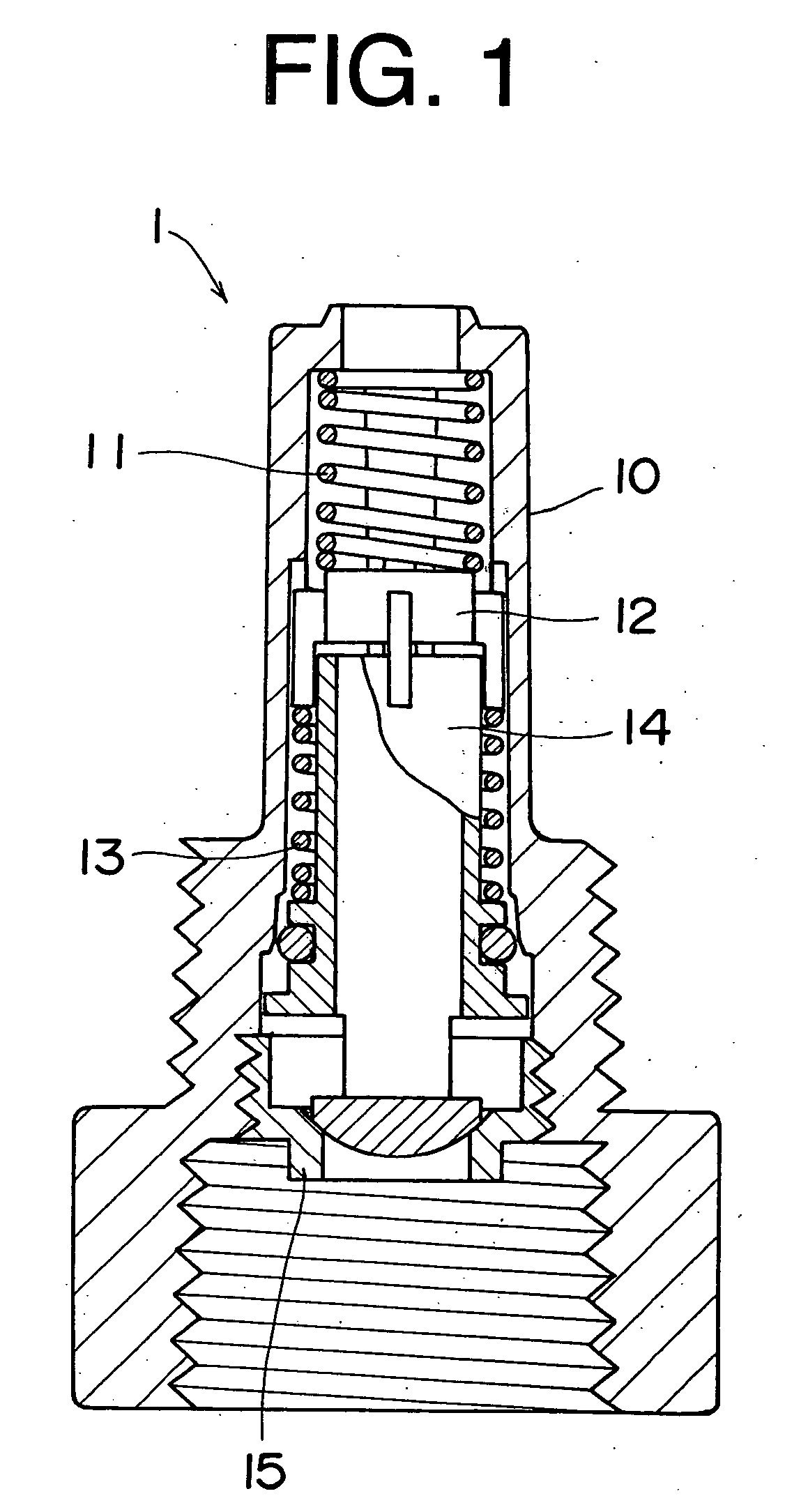
[0029]FIG. 1 illustrates a flow control valve (or a pressure regulator) of the invention in the form of a partial sectional view, and FIG. 2 illustrates each of parts constituting the flow control valve of FIG. 1.

[0030] In FIGS. 1 and 2, the flow control valve 1 of the invention is composed of a cylindrical housing 10 and control means comprising an upper spring 11, a floating cover disc 12, a lower spring 13, a floating inner hollow cylinder valve 14, and a valve seat 15 arranged within the cylindrical housing 10. Both of the upper spring 11 and lower spring 13 preferably are coil springs. Each coil spring can be composed of plural coil spring units, such as a combination of a strong coil spring unit and a weak coil spring unit. The plural coil spring units can contain a joint for combining the spring units.

[0031]FIG. 3 illustrates the cylindrical housing 10 of the flow c...


PUM


Abstract

A flow control valve favorably employable for sprinkler is composed of a cylindrical housing and control means comprising an upper spring, a floating cover disc, a lower spring, a floating hollow cylinder valve, and a valve seat arranged within the cylindrical housing, in which the cover disc is composed of a disc body and plural legs attached to a side face of the disc body and extending downwardly; the cylindrical housing is composed of a bottom fluid inlet, a top fluid outlet and a fluid passage and has plural guides for vertical movement of the legs of the cover disc on its inner surface; the cylinder valve is detachably placed on the valve seat and has an upper opening, a bottom cap, a flange formed in a lower portion of the valve and a side opening formed in a portion lower than the flange; the upper spring is in contact with the top outlet of the housing at its upper end and with an upper surface of the disc body of the cover disc at its lower end; the lower spring is arranged around the cylinder valve, in contact with lower ends of the plural legs of the cover disc at its upper end, and is in contact with the flange of the cylinder valve at its lower end; and the valve seat fixed to the housing in a lower portion.

Description

FIELD OF THE INVENTION [0001] This invention relates to a flow control valve and more particularly to a flow control valve which functions through pressure compensation. BACKGROUND OF THE INVENTION [0002] A sprinkler for irrigation such as pop-up lawn faucet is generally equipped with a flow control valve (or a pressure regulator). Sprinklers installed in different places generally receive water of different pressures. In more detail, the water of different pressures are supplied to sprinklers which are placed at different distances from the source of water or which are placed at different heights. If one sprinkler is placed very near the water source and other sprinkler is placed far from the water source, the former sprinkler receives water of high pressure and sprays a large amount of water rapidly, while the latter sprinkler receives water of low pressure and sprays only a small amount of water slowly. If one sprinkler is placed on a field and other sprinkler is placed on a hill...

Claims


Application Information

Patent Timeline
IPC IPC(8): B05B15/10
CPCF16K1/12B05B15/10B05B15/74
Inventor MIYAKE, YOSHIAKI
Owner NANKAI
Why Eureka
Try Eureka