
Sound source separating device, method, and program

a separation device and sound source technology, applied in the direction of transducer details, instruments, speech analysis, etc., can solve the problems of inability to generate filters to satisfy constraints, performance deterioration, and inability to obtain signals sufficiently separated using output filters

Inactive Publication Date: 2007-09-27
HITACHI LTD
View PDF1 Cites 17 Cited by
  • Summary
  • Abstract
  • Description
  • Claims
  • Application Information

AI Technical Summary

Benefits of technology

[0007]According to the present invention, even in an environment in which the number of sound sources exceeds the number of microphones and some background noises, echoes, and reverberations occur, with high S / N, sounds can be separated for each of sound sources. As a result, conversations are enabled in easy-to-hear sounds in hands-free conversions and the like.

Problems solved by technology

The independent component analysis has a problem that performance deteriorates when the number of sound sources exceeds the number of microphones.
However, when the number of sound sources exceeds the number of microphones, since the number of restrictions exceeds the number of microphones, filters to satisfy the constraints cannot be generated, and signals sufficiently separated cannot be obtained using outputted filters.
The l1 norm minimization method has a problem that, since it is assumed that noises other than sound sources do not exist, performance deteriorates in the environment where noises other than voices, such as echo and reverberation, exist.

Method used


Image

  • Sound source separating device, method, and program
  • Sound source separating device, method, and program
  • Sound source separating device, method, and program

Examples


first embodiment

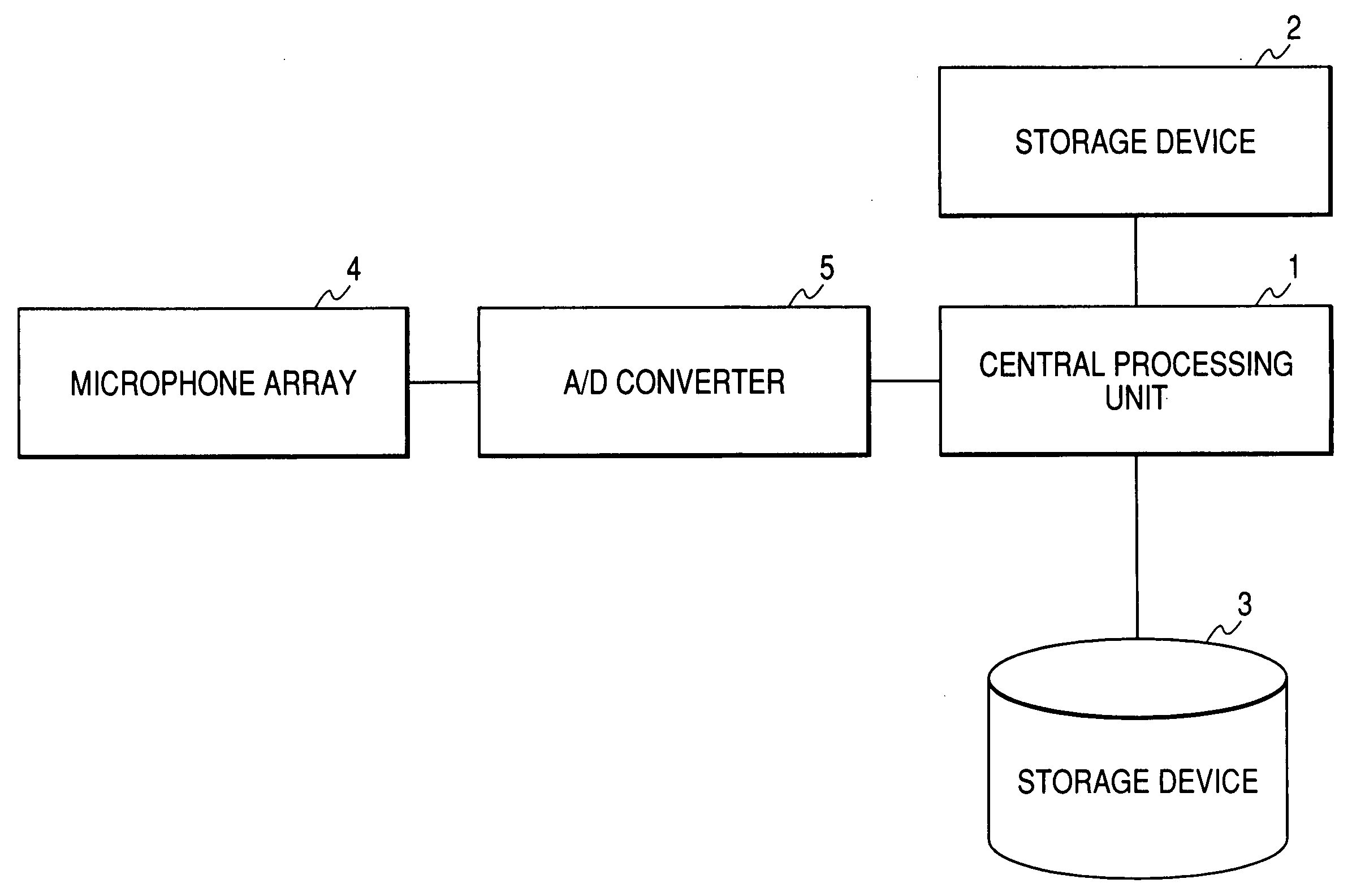
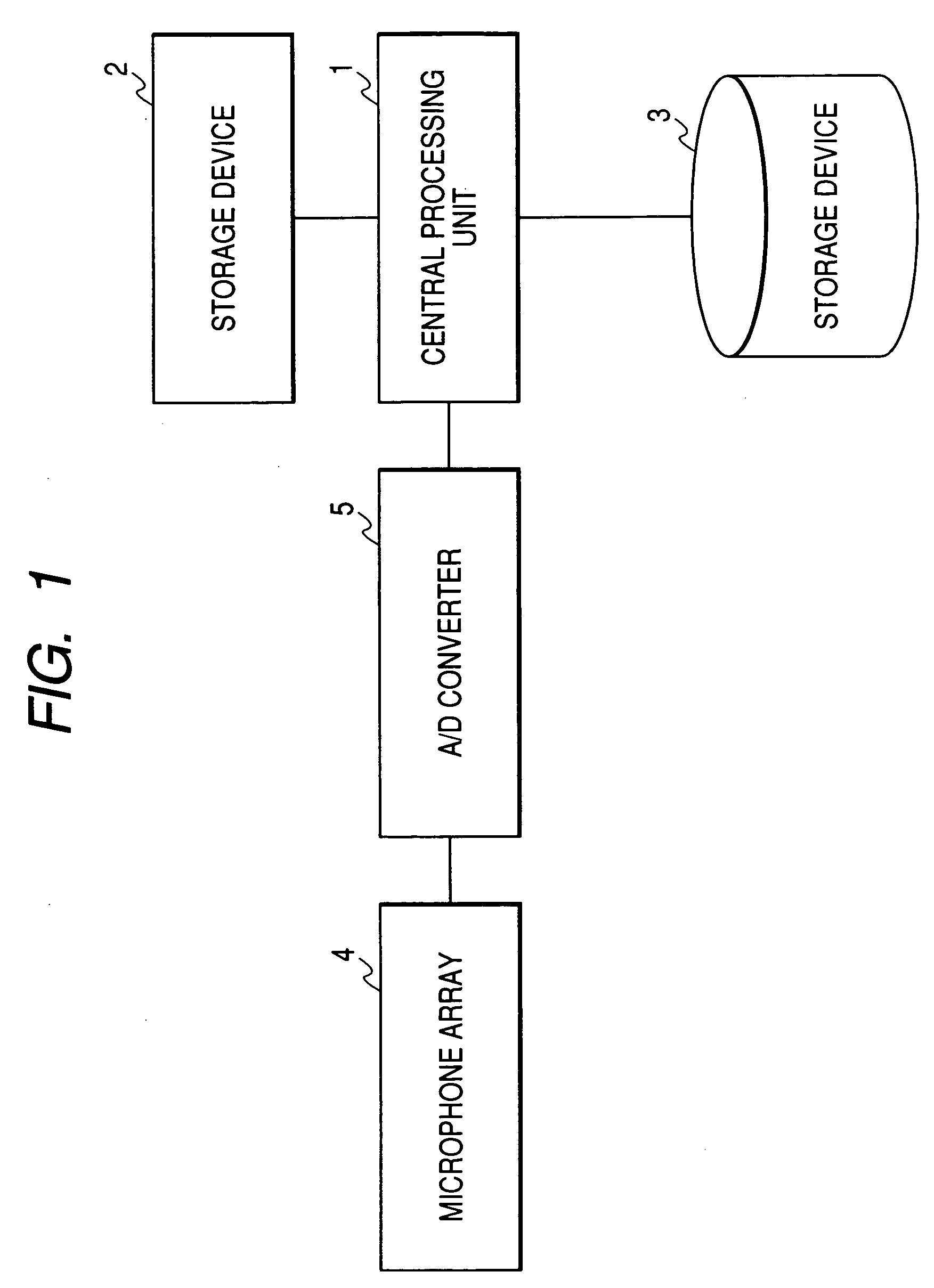
[0011]FIG. 1 shows a hardware configuration of this embodiment. All calculations included in this embodiment are performed within the central processing unit 1. A storage device 2 is a work memory constructed by a RAM, for example, and all variables used during calculations may be placed on one or more of the storage device 2. Data and programs used during calculations are stored in a storage device 3 constructed by a ROM, for example. A microphone array 4 comprises at least two or more microphone elements. The individual microphone elements measure an analog sound pressure value. It is assumed that the number of microphone elements is M.

[0012]An A / D converter converts an analog signal into a digital signal (sampling), and can synchronously sample signals of M or more channels. An analog sound pressure value of each of microphone elements captured in the microphone array 4 is sent to the A / D converter 5. The number of sounds to be separated is set in advance, and stored in the stora...


PUM


Abstract

Conventional independent component analysis has had a problem that performance deteriorates when the number of sound sources exceeds the number of microphones. Conventional l1 norm minimization method assumes that noises other than sound sources do not exist, and is problematic in that performance deteriorates in environments in which noises other than voices such as echoes and reverberations exist. The present invention considers the power of a noise component as a cost function in addition to an l1 norm used as a cost function when the l1 norm minimization method separates sounds. In the l1 norm minimization method, a cost function is defined on the assumption that voice has no relation to a time direction. However, in the present invention, a cost function is defined on the assumption that voice has a relation to a time direction, and because of its construction, a solution having a relation to a time direction is easily selected.

Description

CLAIM OF PRIORITY[0001]The present application claims priority from Japanese application JP 2006-055696 filed on Mar. 2, 2006, the content of which is hereby incorporated by reference into this application.FIELD OF THE INVENTION[0002]The present invention relates to a sound source separating device that separates sounds for sound sources using two or more microphones when multiple sound sources are placed in different positions, a method for the same, and a program for instructing a computer to execute the method.BACKGROUND OF THE INVENTION[0003]A sound source analysis method based on independent component analysis is known as a technology for separating a sound for each of several sound sources (e.g., see A. Hyvaerinen, J. Karhunen, and E. Oja, “Independent component analysis,” John Wiley & Sons, 2001). Independent component analysis is a sound source separation technology that advantageously uses the fact that source signals of sound sources are independent between the sound sourc...

Claims


Application Information

Patent Timeline
Patent Type & Authority Applications(United States)
IPC IPC(8): H04R3/00H04R1/02G10L21/028G10L21/0308G10L25/90
CPCH04R3/005
Inventor TOGAMI, MASAHITOAMANO, AKIOSUMIYOSHI, TAKASHI
Owner HITACHI LTD
Learn More