
Direct drive hose reel assembly

Inactive Publication Date: 2007-09-13
SPRAY NOZZLE ENG
View PDF8 Cites 15 Cited by
  • Summary
  • Abstract
  • Description
  • Claims
  • Application Information

AI Technical Summary

Benefits of technology

[0010] It is also preferred that the riser have fluid pathway components into and out of the spool which components can be readily attached and detached from the spool without first removing it from the hub.
[0011] It is further preferred that the spool have an interior surface about which a hose c

Problems solved by technology

The drive mechanisms of such reels have conventionally included chain and sprocket type drives and the like and their inherent safety problems.

Method used


Image

  • Direct drive hose reel assembly
  • Direct drive hose reel assembly
  • Direct drive hose reel assembly

Examples


Embodiment Construction

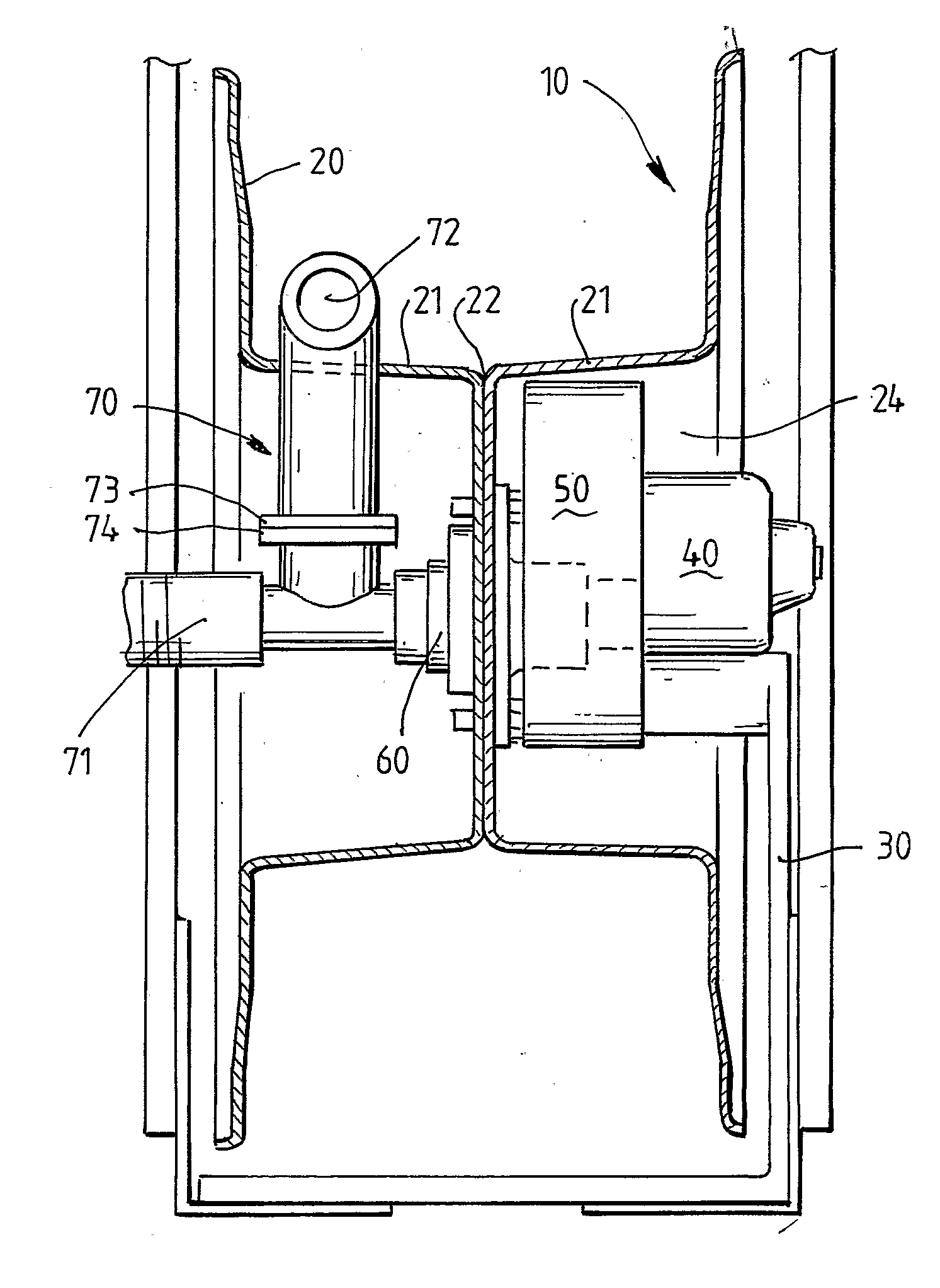
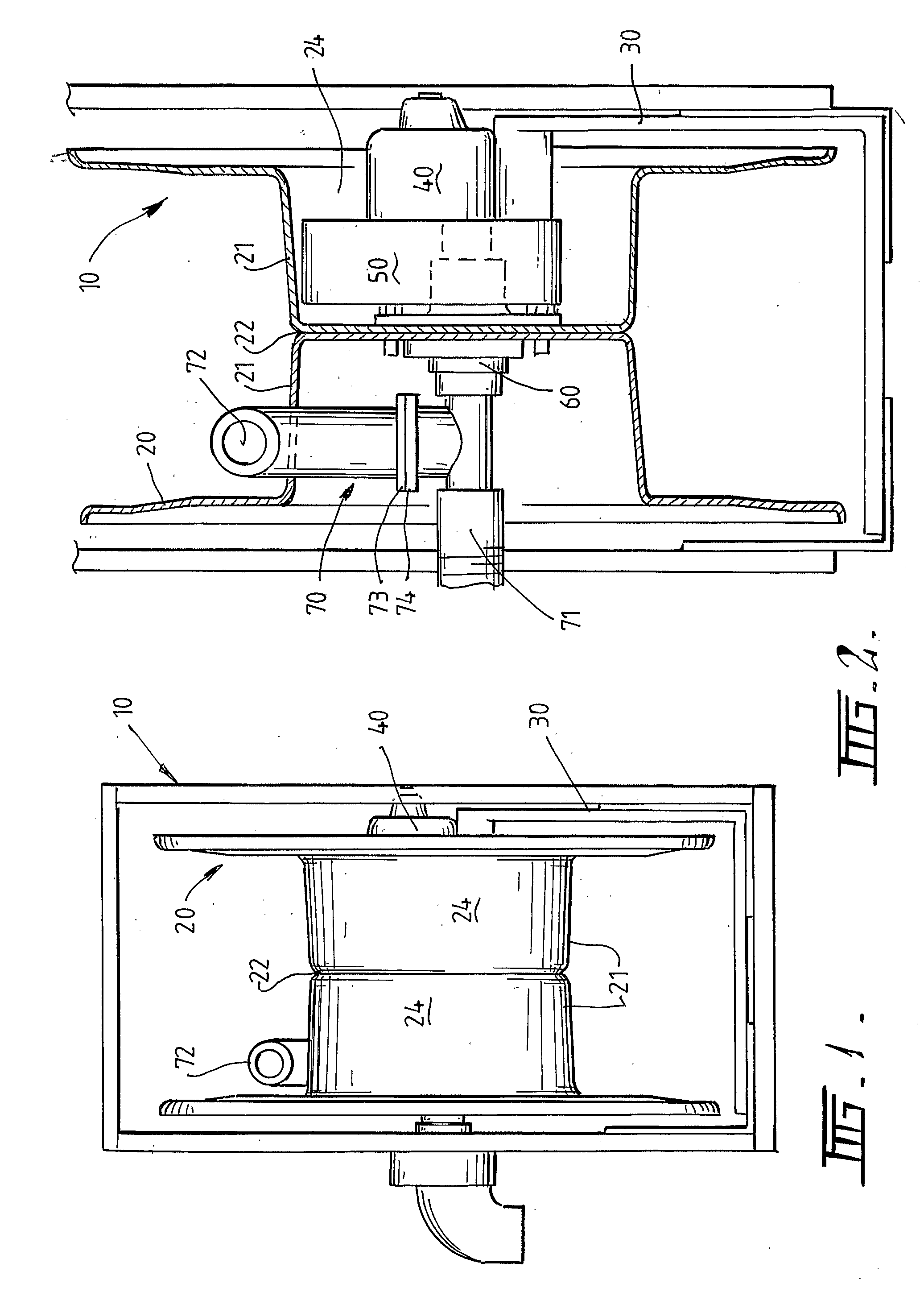
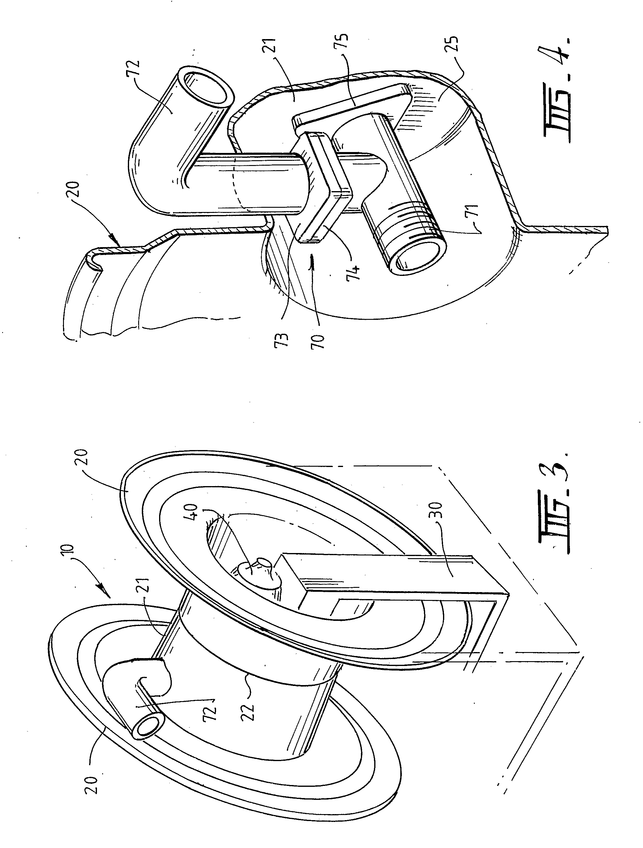
[0017] In one embodiment of the invention a hose reel assembly 10 as shown in FIG. 2 is provided in which the reel spool 20 is supported on a mounting frame 30 or support associated with a single automotive style stub axle, bearing and five stud hub assembly. By this means simplicity of servicing is provided and assembly and disassembly of the reel is accomplished in a similar manner to changing a vehicle wheel.

[0018] In addition the factory assembly of this reel assembly is time effective due to the use of the 5 stud hub construction. Many previous reels have used two bearing blocks on each side of the hub shaft that require general axial alignment and add to the width of the assembly. The design of the present invention eliminates this requirement.

[0019] Additionally other reels rely on the bearing assembly within the drive unit to support the spool whereas the hub loads in the reel system of the invention are taken up by the support and are not transmitted to the bearings of th...


PUM


Abstract

A hose reel assembly includes a unitary support member and a hose reel spool, which as a riser connected therethrough for providing a fluid path. The unitary support member includes an axle, bearing and hub assembly, with an integrated frame that encompasses a bearing assembly and a drive unit housing.

Description

AREA OF THE INVENTION [0001] This invention relates to the area of reels for storing tubing and in particular to hose reels for all hose applications. The present invention relates to a hose reel assembly having an integrated automotive hub and bearing assembly and frame such that a unitary system is provided. BACKGROUND TO THE INVENTION [0002] Traditional mechanical hose reels, even for industrial applications, provided direct hand cranked systems with bearings to assist in the rewind. These systems provided spools for housing the hose mounted on a frame supported between two axial bearing assemblies with a crank means located at one end. [0003] To assist in the rewind process this type of hose reel came to be provided with is either electric motors or compressed air or hydraulic motors. Such systems might be geared or not but all feature a spool type housing of some type mounted inside a support frame which is adapted to both support and drive a specific spool. The drive mechanism...

Claims


Application Information

Patent Timeline
IPC IPC(8): B65H75/34B65H75/38B65H75/44
CPCB65H75/4481B65H75/4478Y10T137/6932
Inventor MORGAN, STUARTMORGAN, SEAN
Owner SPRAY NOZZLE ENG
Learn More