Mammographic system and breast compression plate for use in mammographic system

a breast compression plate and mammography technology, applied in mammography, medical science, diagnostics, etc., can solve the problems of both the operator and the examiner being liable to feel pain when the hand is removed, and the operator still finds it difficult to remove the hand from the breast compression plate, etc., to achieve the effect of easy removal

Inactive Publication Date: 2007-09-06
FUJIFILM CORP
View PDF3 Cites 12 Cited by
  • Summary
  • Abstract
  • Description
  • Claims
  • Application Information

AI Technical Summary

Benefits of technology

[0010]It is a general object of the present invention to provide a breast compression plate, which allows the operator's hand to be removed easily while a breast is being secured in a desired position on the breast compression plate and while the breast is compressed by the breast compression plate. The present invention also has the object of providing a mammographic system, which incorporates such a breast compression plate.
[0011]Another object of the present invention is to provide a breast compression plate that reduces the burden on the operator who works with the breast compression plate, as well as the burden on the examinee whose breast is being compressed by the breast compression plate, together with a mammographic system incorporating such a breast compression plate.
[0012]Still another object of the present invention is to provide a breast compression plate which is capable of positioning a breast of an examinee highly accurately, together with a mammographic system incorporating such a breast compression plate.

Problems solved by technology

After the breast is compressed and secured in position by the breast compression plate, it is hard for the operator to remove his or her hand, and both the operator and the examinee are liable to feel pain when the hand is removed.
Therefore, the operator still finds it hard to remove his or her hand from the breast compression plate.
However, there is nothing taken into account to make it easy for the operator to remove his or her hand from the breast compression paddle.
Therefore, the operator finds it hard to remove his or her hand from the breast compression paddle after the angularly adjusted breast compression paddle has been secured in place.
Consequently, if the breast compression paddle is angularly loosened to allow the operator to remove his or her hand more easily, then the breast that has been secured in position tends to be displaced.

Method used


Image

  • Mammographic system and breast compression plate for use in mammographic system
  • Mammographic system and breast compression plate for use in mammographic system
  • Mammographic system and breast compression plate for use in mammographic system

Examples


first embodiment

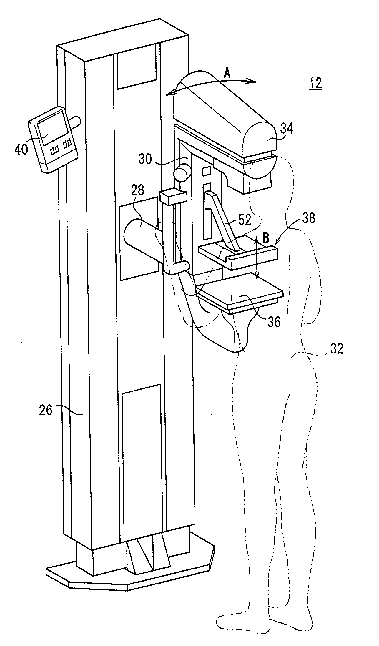
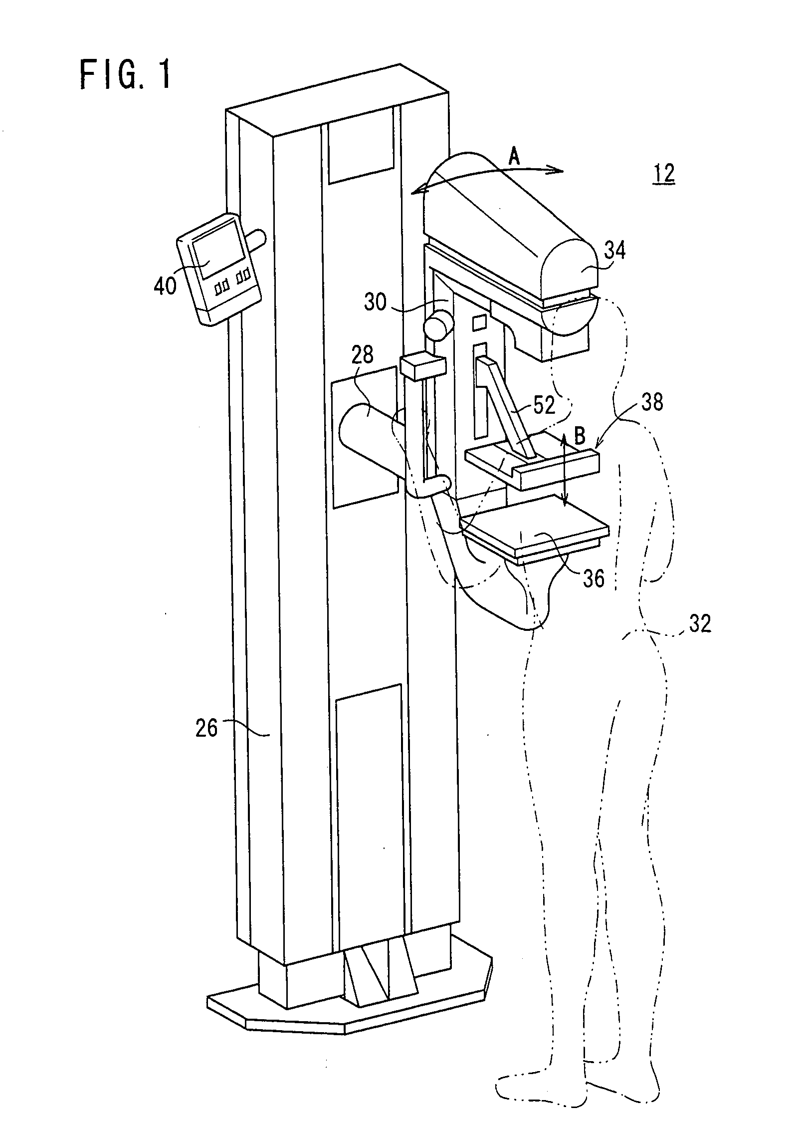
[0035]A mammographic system 12, shown in FIG. 1, according to the present invention serves to capture radiation image information of a breast, which is the subject of examination.

[0036]As shown in FIG. 1, the mammographic system 12 includes an upstanding base 26, a vertical arm 30 fixed to a horizontal swing shaft 28 disposed substantially centrally on the base 26, a radiation source housing unit 34 fixed to an upper end of the arm 30, an image capturing base 36 housing therein a solid-state detector for detecting radiation that has passed through the examinee 32 and which is fixed to a lower end of the arm 30, and a breast compression plate 38 for compressing and holding the breast of the examinee 32 against the image capturing base 36. The radiation source housing unit 34 stores a radiation source for applying radiation to the breast of the examinee 32. The image capturing base 36 houses therein a solid-state detector for detecting the radiation that has passed through the examine...

second embodiment

[0063]A breast compression plate according to the present invention shall be described below with reference to FIGS. 8 through 10. Reference characters in FIGS. 8 through 10, which are identical to those shown in FIGS. 1 through 7, are intended to denote identical or similar structural details having identical or similar functions and advantages. Such identical reference characters, denoting identical or similar structural details having identical or similar functions and advantages, also are applicable to the other embodiments.

[0064]A breast compression plate 64 according to the second embodiment differs from the breast compression plate 38 according to the first embodiment in that helical torsion springs 66 (resilient members) are disposed respectively near the hinges 58. Further, the breast compression plate 64 is free of the lock mechanisms 62.

[0065]The helical torsion springs 66 act between the movable flaps 60a, 60b and the base bar 56a so as to normally bias the movable flaps...

third embodiment

[0069]A breast compression plate according to the present invention will be described below with reference to FIGS. 11 through 13.

[0070]The breast compression plate 68 according to the third embodiment differs from the breast compression plate 38 according to the first embodiment in that it has a fixed base 70 and movable flaps 72a, 72b, in place of the fixed base 56 and the movable flaps 60a, 60b, and also is free of the lock mechanisms 62.

[0071]The fixed base 70 has a main compression foot 70b including two laterally spaced mounts (second mounts) 76, which are spaced or offset from an upper surface of the main compression foot 70b by a predetermined distance toward the image capturing base 36, at an end of the main compression foot 70b remote from the base bar 56a, i.e., at an end of the main compression foot 70b closer to the nipple region of the breast 44 as it is compressed by the main compression foot 70b. Helical springs 74 (extensible and contractible members) have respectiv...


PUM


Abstract

A mammographic system for capturing a radiation image of the breast of an examinee includes an image capturing base, having a radiation image information acquisition unit for acquiring information of the radiation image, and a breast compression plate for compressing the breast against the image capturing base. The breast compression plate has a fixed base for compressing and securing the breast, the fixed base includes a surface to be held against a chest wall of the examinee, and a movable flap connected to the fixed base, which is displaceable in order to release the breast.

Description

BACKGROUND OF THE INVENTION[0001]1. Field of the Invention[0002]The present invention relates to a mammographic system for capturing a radiation image of the breast of an examinee, together with a breast compression plate for use in such a mammographic system.[0003]2. Description of the Related Art[0004]Generally, mammographic systems employ a breast compression plate for compressing the breast of an examinee against an image capturing base. The breast compression plate is disposed between a radiation source that emits radiation and the image capturing base, which incorporates a detector for detecting the radiation emitted from the radiation source. The breast compression plate compresses the breast, which is to be imaged, into a flatter shape having a substantially uniform thickness, so that a better radiation image of the breast can be obtained.[0005]Japanese Laid-Open Patent Publication No. 4-64346 discloses a breast compression mechanism for lowering a breast compression plate m...

Claims


Application Information

Patent Timeline
Patent Type & Authority Applications(United States)
IPC IPC(8): A61B6/04
CPCA61B6/502A61B6/0414
Inventor OKADA, NAOYUKISENDAI, TOMONARI
Owner FUJIFILM CORP
Why Eureka
Try Eureka