Display device

a display device and display technology, applied in the field of display devices, can solve the problems of increasing power consumption by that amount, affecting the quality of display, and increasing the circuit scale, so as to reduce the blurring of moving pictures, reduce the luminance display, and reduce the effect of low luminance display

Inactive Publication Date: 2007-08-23
PANASONIC LIQUID CRYSTAL DISPLAY CO LTD +1
View PDF8 Cites 14 Cited by
  • Summary
  • Abstract
  • Description
  • Claims
  • Application Information

AI Technical Summary

Benefits of technology

[0014] An object of the present invention is to provide a display device in which moving picture blurring is reduced with a small circuit scale while suppressing luminance falling, contrast falling and an increase in power required for light emission.
[0017] According to the present invention, the voltage generation circuit generates different gray scale voltages depending on the field periods in one frame period, and the gray scale voltages are changed over and used depending on the field period. As a result, high luminance display and low luminance display can be changed over and displayed in one frame period. Therefore, the moving picture blurring can be reduced while suppressing the luminance falling and the contrast falling.
[0018] According to the present invention, the display device reduced in moving picture blurring can be implemented by only changing over and using the voltage generation circuit. Therefore, the circuit scale can be made small.

Problems solved by technology

Although the moving picture blurring can be remedied by applying the above-described technique, it is known that problems described hereafter are posed by applying the technique.
If it is attempted to generate more accurate data, therefore, the circuit scale becomes large.
On the contrary, if the circuit scale is held down, interpolation generation mistakes occur, resulting in a fear of a remarkably lowered display quality.
If the backlight luminance is raised for the black display data insertion system in order to compensate the luminance fall, the power consumption increases by that amount and much labor is needed to take a measure against the generated heat.
In addition, since the absolute value of light leak in the black display increases, contrast falling is caused.
As regards the system in which black is inserted only in images having low luminance, the contrast extremely falls in low luminance images or there is unnaturalness that the luminance suddenly falls on a luminance boundary across which black is inserted and black is not inserted.

Method used


Image

  • Display device
  • Display device
  • Display device

Examples


first embodiment

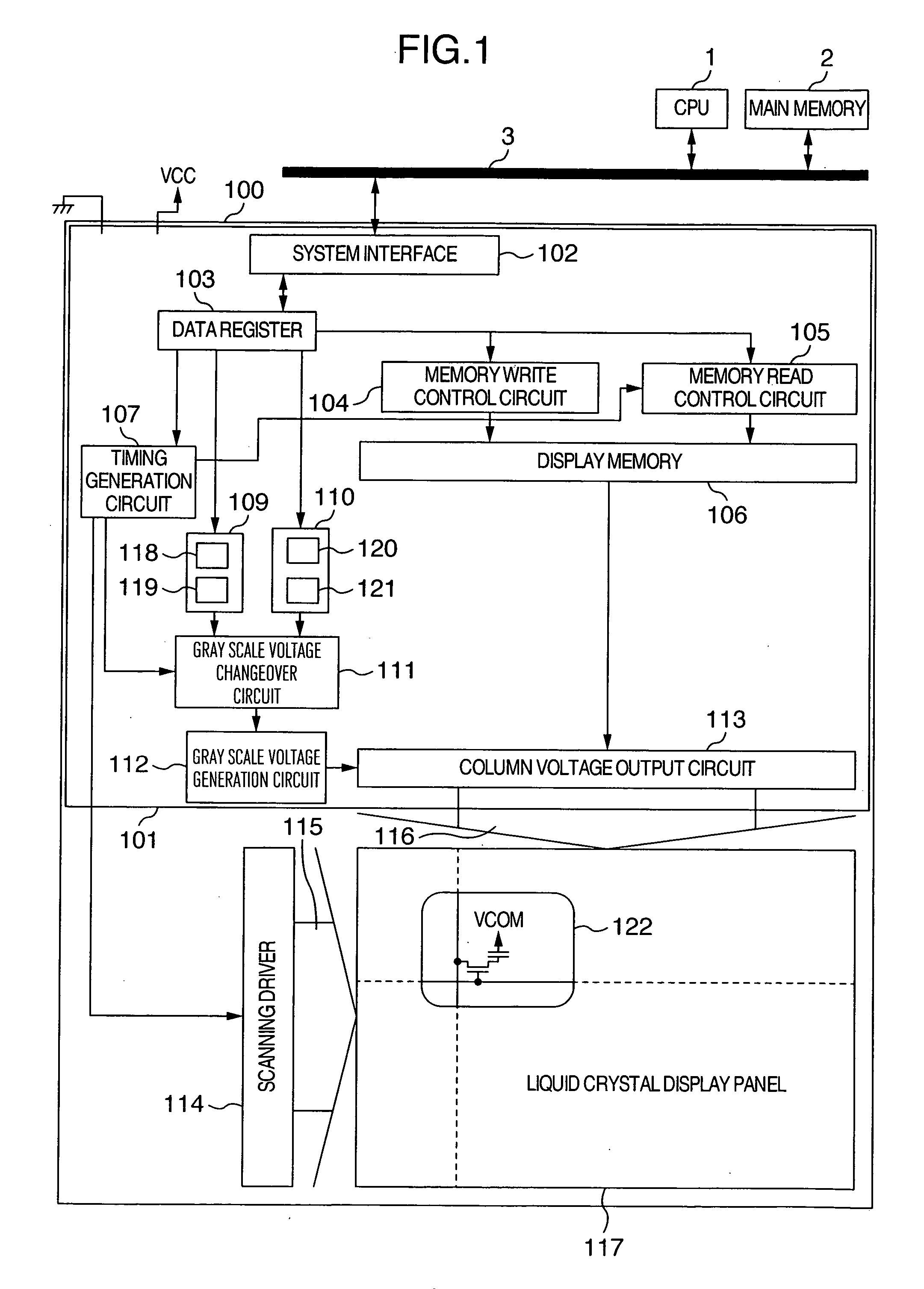
[0039] Hereafter, a first embodiment which is one of best embodiments of the present invention will be described.

[0040]FIG. 1 is a block diagram of a display device in the first embodiment. In FIG. 1, reference numeral 100 denotes a display device, 101 a column drive circuit (data driver) for outputting a gray scale voltage according to display data which indicates a gray scale level, 117 a liquid crystal display panel, and 114 a scanning driver for sequentially scanning pixel lines on the liquid crystal display panel 117, for example, every horizontal period. In the column drive circuit 101, reference numeral 102 denotes a system interface for receiving display data, control signals (such as synchronizing signals) and control data (such as the γ value) from external systems (CPU 1 and a main memory 2) via a system bus 3, 103 a data register for setting control data, 107 a timing generation circuit for generating timing signals (such as the horizontal synchronizing signal and the ve...

second embodiment

[0061] Operation in the present second embodiment will now be described with reference to FIG. 6.

[0062] In FIG. 6, the field signal is output at a frequency which is three time as high as that of the frame signal.

[0063]FIG. 6 also shows the line alternating operation. The polarity of the voltage applied to the liquid crystal is changed over between the positive polarity and the negative polarity every line of the liquid crystal. Over one frame period, the same lines have the same polarity. If the frame has changed, the same lines have opposite polarities. For example, it is supposed that a first column in a first field period in a first frame period has “H”, i.e., the negative polarity as shown in FIG. 4. Then, a first column in a second field period in the first frame period has “H”, i.e., the negative polarity. A first column in a third field period in the first frame period has “H”, i.e., the negative polarity. A first column in a first field period in a second frame period has ...


PUM


Abstract

A display device in which one frame period is divided to a plurality of field periods, it is made possible to set gray scale voltage groups of a plurality of kinds depending on the field period, and a gray scale voltage is equipped with a function of generating and outputting gray scale voltage groups of different kinds according to the field period.

Description

INCORPORATION BY REFERENCE [0001] The present application claims priority from Japanese application JP2006-030416 filed on Feb. 8, 2006, the content of which is hereby incorporated by reference into this application. BACKGROUND OF THE INVENTION [0002] The present invention relates to a hold-type display device such as a liquid crystal display device, an organic EL (Electro Luminescence) display or a LCOS (Liquid Crystal On Silicon) display. In particular, the present invention relates to a display device suitable for display of a moving picture. [0003] If displays are classified especially from the viewpoint of moving picture display, the displays are divided broadly into impulse-response type (hereafter referred to as impulse-type) displays and hold-response type (hereafter referred to as hold-type) displays. In the impulse-type displays, luminance response falls from immediately after scanning like after-glow characteristics in cathode-ray tubes. In the hold-type displays, luminan...

Claims


Application Information

Patent Timeline
IPC IPC(8): G09G3/36G02F1/133G09G3/20G09G3/30H04N5/66H04N5/70
CPCG09G3/2011G09G3/2025G09G2320/0261G09G3/3648G09G3/2077
Inventor KATAYAMA, YUKARIKUDO, YASUYUKIMATSUDO, TOSHIMITSU
Owner PANASONIC LIQUID CRYSTAL DISPLAY CO LTD
Why Eureka
Try Eureka