
Roll-up screen partition

a screen and partition technology, applied in the direction of shutters/movable grilles, towers, buildings, etc., can solve the problems of easy soiled or damaged panels, time-consuming and inconvenient, etc., and achieve the effect of convenient rolling up and protecting

Inactive Publication Date: 2007-08-23
GEMMY IND CORP
View PDF6 Cites 59 Cited by
  • Summary
  • Abstract
  • Description
  • Claims
  • Application Information

AI Technical Summary

Benefits of technology

[0008] The main objective of the present invention is to provide a roll-up screen partition, which can be easily rolled up and protected when not in use.

Problems solved by technology

However, with a conventional screen partition, the panel must be manually rolled up around one of the posts for storage and unrolled for use, which is both time consuming and inconvenient.
Furthermore, the panel can be easily soiled or damaged because it is exposed and unprotected.

Method used


Image

  • Roll-up screen partition
  • Roll-up screen partition
  • Roll-up screen partition

Examples


first embodiment

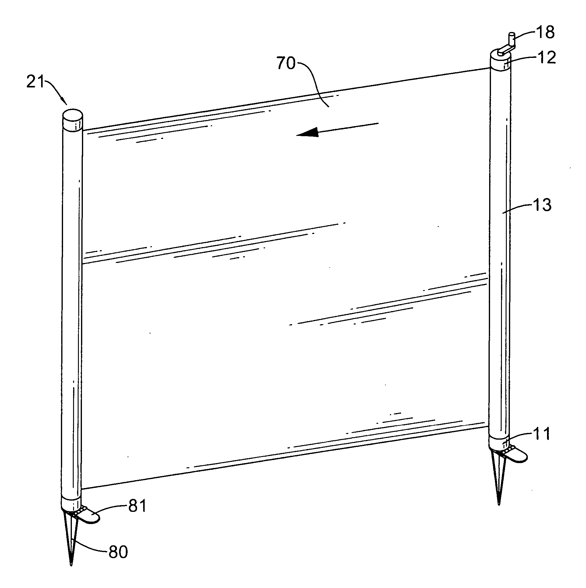
[0018] With reference to FIG. 1, a roll-up screen partition is composed of a post (21), a reel (10) and a panel (70). A first end of the panel (70) is mounted to the reel (10) and a second end of the panel (70) is mounted to the post (21).

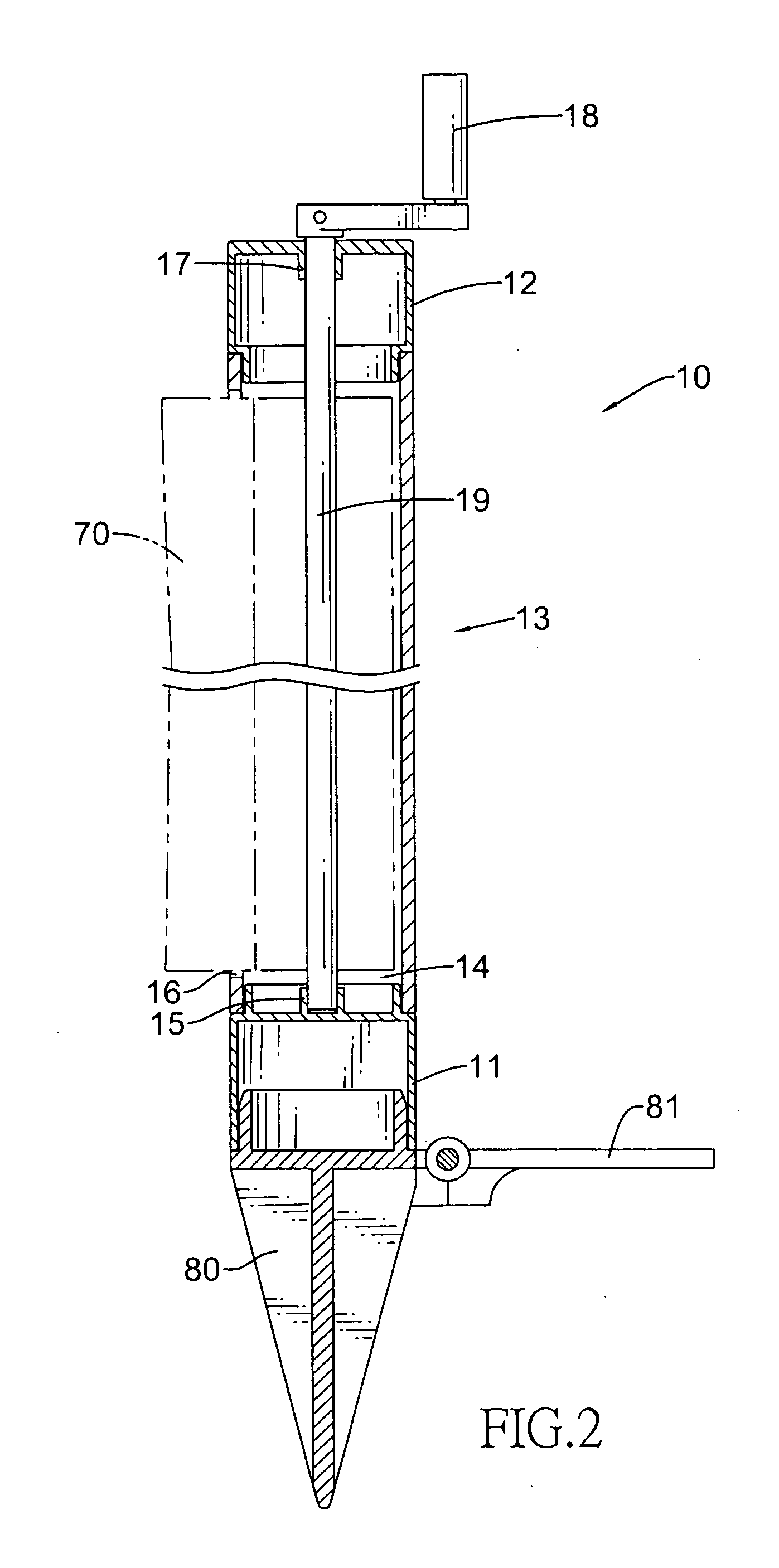
[0019] With reference to FIG. 2, the reel (10) has an outer tube (13). A lower cap (11) is provided on a lower end of the outer tube (13) and an upper cap (12) is provided on an upper end of the outer tube (13). In the first embodiment, the upper cap (12) is partially inserted into the upper end of the outer tube (13) and the lower cap (11) is partially inserted into the lower end of the outer tube (13). In other embodiments, the upper and the lower caps (12, 11) can also be mounted respectively on the outer tube (13) by fasteners or other forms of engagement.

[0020] A hole (17) is axially defined in the upper cap (12) and a cup (15), with an open end defined upward, is axially formed on a top surface of the lower cap (11). An inner space (14) is d...

second embodiment

[0022] The reel (20) in the second embodiment is composed of an outer tube (50) with a pawl assembly (90). An inner space (51) is defined inside the outer tube (50). A slot (52) is longitudinally defined in a sidewall of the outer tube (50) and communicates with the inner space (51). The outer tube (50) has an upper cap (40) mounted on an upper end thereof and a lower cap (30) mounted on a lower end thereof. The upper cap (40) has an open top and a through hole in the bottom. The lower cap (30) has an open bottom and a through hole in the top. A spring housing (62) is mounted rotatably inside the upper cap (40). The spring housing (62) has an open top and a protrusion (61) axially formed on a bottom that is mounted through the through hole of the upper cap (40). Multiple unidirectional teeth (65) are formed around the periphery of the protrusion (61). Two end plates are mounted over the open top of the upper cap (40) and the open bottom of the lower cap (30), respectively. A lower l...


PUM


Abstract

A roll-up partition has a post, a reel and a panel. The reel has an outer tube which has an inner space defined in a center of the outer tube and slot is longitudinally defined in a periphery of the outer tube and in communication with the inner space. A rod is rotatably received in the inner space. A first end of the panel is connected to the reel and a second end of the panel is connected to the post. The panel can be easily and quickly rolled up into the reel of the present invention wherein the panel is protected from damage and contamination.

Description

BACKGROUND OF THE INVENTION [0001] 1. Field of the Invention [0002] The present invention relates to a screen partition, and more particularly to a screen partition that can be rolled up on a reel for storage or transport. [0003] 2. Description of the Related Art [0004] At exhibitions, whether indoors or outdoors, portable partitions are erected to divide the exhibition area into separate spaces or placed to direct people in a certain direction. The partitions can be made of rigid or soft panels. Many portable partitions use soft flexible panels or screens for convenient storage. [0005] A conventional screen partition comprises a panel and two posts. The panel is securely mounted at two ends on the two posts, respectively. The posts are positioned in a desired location and the panel is extended to form a wall to divide an area. [0006] However, with a conventional screen partition, the panel must be manually rolled up around one of the posts for storage and unrolled for use, which is...

Claims


Application Information

Patent Timeline
Patent Type & Authority Applications(United States)
IPC IPC(8): A47G5/02A47H1/00
CPCA47G5/02E06B9/08E04H12/2215E01F13/028
Inventor HSU, SHENG-HUNG
Owner GEMMY IND CORP
Learn More