
Semi-removable window frame assembly

a window frame and semi-fixed technology, applied in the direction of wing arrangements, doors/windows, building components, etc., can solve the problems of fixed sash, difficult to reach the central windows from either end, and not being able to fully use design, etc., to achieve the effect of low cos

Inactive Publication Date: 2007-08-16
GUILLEMETTE CHRISTIAN
View PDF20 Cites 11 Cited by
  • Summary
  • Abstract
  • Description
  • Claims
  • Application Information

AI Technical Summary

Benefits of technology

[0025] As can be appreciated, a window frame assembly according to the present invention can advantageously combine the simplicity and low cost of a single-hung window, and the ease of installation and access to the exterior side of both sashes.

Problems solved by technology

For single-hung windows, wherein only the lower sash is openable, it is much more difficult to access the exterior face of the glazing in the upper, fixed sash.
If hanging out of the window in this manner is not feasible, the washer must approach the window from outside the building.
When opened, however, crank windows only give access to the exterior face of one of their neighbouring windows.
Furthermore, if a large number of these tall, thin windows are employed then it becomes quite difficult to reach the central windows from either end.
Thus far, a design has not been produced which can fully make use of the advantages of both the single-type and double-type configurations of various types of windows.
Also known in the art are the various disadvantages associated with these types of conventional window frames.
For example, such designs can be as complex and difficult to manufacture, and hence expensive, as standard double-hung windows.
Moreover, the engagement between the removable upper sash and the outer casing are often too loose to provide adequate sealing against the elements or insulation.

Method used


Image

  • Semi-removable window frame assembly
  • Semi-removable window frame assembly
  • Semi-removable window frame assembly

Examples


Embodiment Construction

[0035] In the following description, similar features in the drawings have been given similar reference numerals and in order to lighten the figures, some elements are not referred to in some Figures if they were already identified in a preceding Figure.

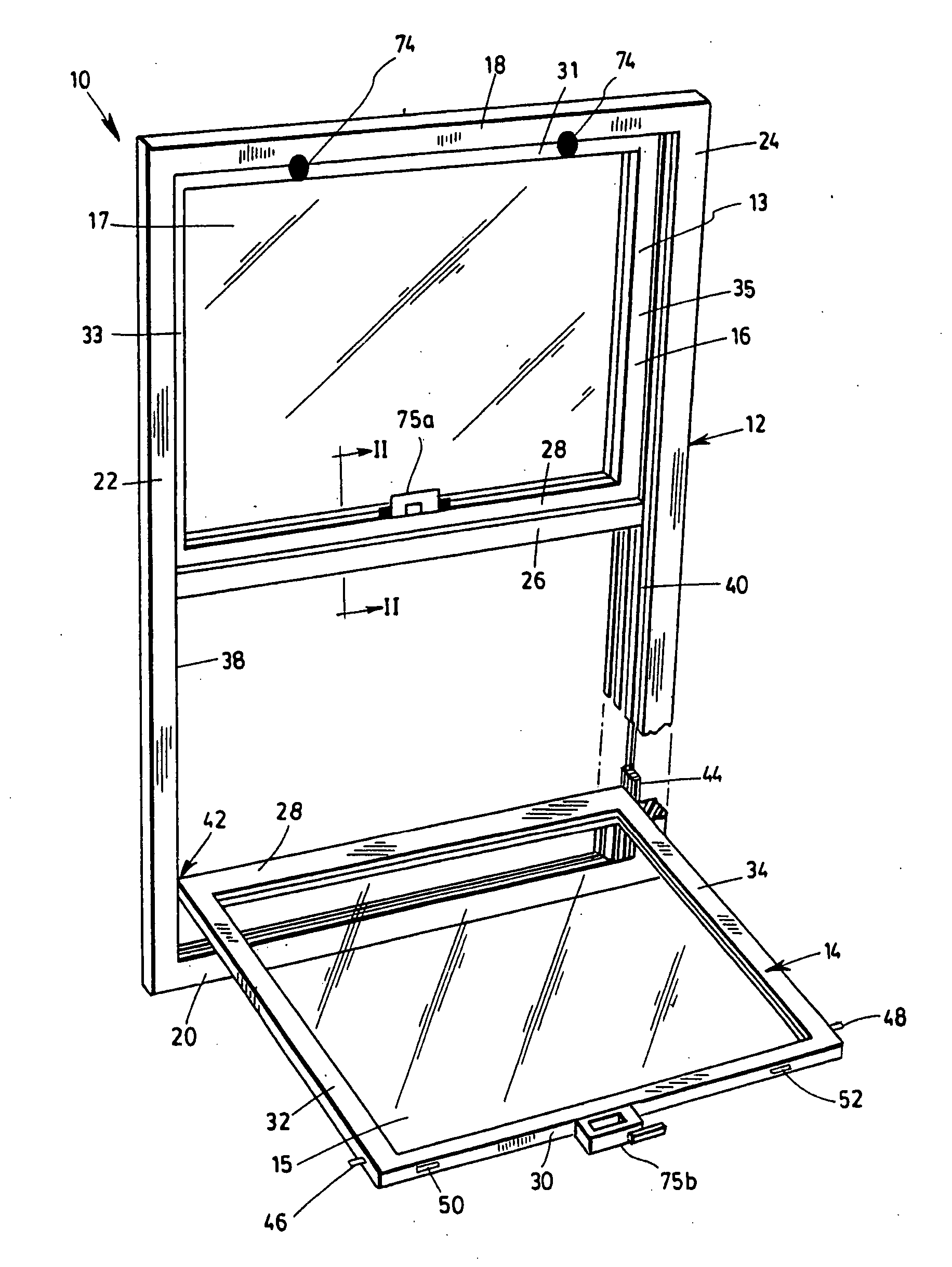
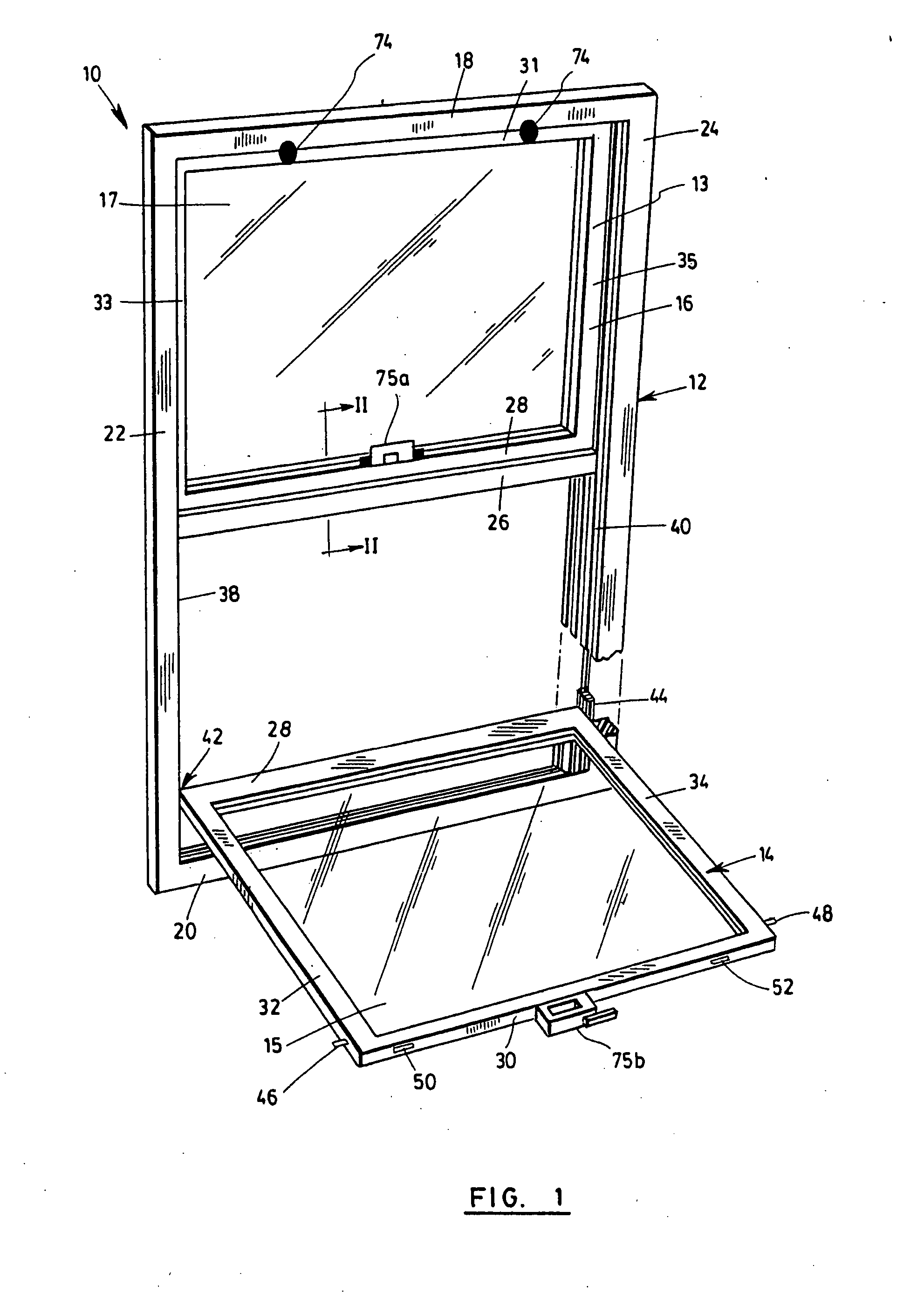
[0036] In FIG. 1, a window frame assembly 10 is illustrated comprising an outer frame 12 which retains a lower, articulated sash 14 and an upper, semi-fixed sash 16. The outer frame 12, also called a casing, is installed in a building wall (not shown). It comprises a frame header 18, a frame sill 20, and left and right vertical frame jambs 22 and 24, which form its upper, lower, left and right sides, respectively. A horizontal cross framing member 26, also called a crossbar, is further provided which extends across the casing 12. The articulated sash 14 comprises a bottom rail 28, a top rail 30, and left and right vertical stiles 32 and 34. The semi-fixed sash similarly comprises a bottom rail 29, a top rail 31, and left and right v...


PUM


Abstract

A window frame assembly is disclosed having an outer frame, an articulated sash retaining a first glazing and a semi-fixed sash retaining a second glazing. The outer frame includes a pair of vertical frame jambs, a frame header, a frame sill, and a horizontal cross framing member extending across the outer frame. The cross framing member has a top face, a bottom face and a groove extending along the top face. The articulated sash includes an articulating engagement with the outer frame and is operable to open with respect to the outer frame. The semi-fixed sash is positionable above the cross framing member and includes a pair of vertical stiles, a top rail, a bottom rail and a lip projecting downwardly from the bottom rail for engaging the groove, and a locking mechanism co-operable with the lip and groove for retaining the semi-fixed sash within the outer frame.

Description

FIELD OF THE INVENTION [0001] The present invention relates generally to the field of windows and window frames. More particularly, it concerns a window frame assembly comprising a semi-fixed sash. BACKGROUND OF THE INVENTION [0002] Modern window frames are presently available in a number of different designs and configurations. Casement, awning, picture, single-hung, double-hung, single-sliding, double-sliding, and bay windows each provide their own set of advantages and disadvantages when considering look, functionality and price. [0003] For example, a conventional double-hung window includes two vertically disposed sashes capable of sliding vertically within the larger window frame. A single-hung window similarly includes two vertically disposed sashes, but only one of which is capable of sliding vertically within the window frame. To make opening the window easier, it is typically the upper sash which is fixed in the frame, and the lower sash which can slide vertically. [0004] I...

Claims


Application Information

Patent Timeline
IPC IPC(8): E06B3/32
CPCE06B3/44E06B3/6621E06B3/5063E06B3/4407
Inventor GUILLEMETTE, CHRISTIAN
Owner GUILLEMETTE CHRISTIAN
Learn More