
Bladder structure of a football

a football and blade technology, applied in the field of blade structure, can solve the problems of football ending up in landfill, the height of the protruding ribs is gradually reduced,

Inactive Publication Date: 2007-08-02
CHANG YEN LI
View PDF6 Cites 42 Cited by
  • Summary
  • Abstract
  • Description
  • Claims
  • Application Information

AI Technical Summary

Benefits of technology

[0006] The primary objective of the present invention is to provide an improved bladder having thereon protruding ribs on an outer periphery o

Problems solved by technology

However, due to frequent friction with the ground surface, a height of the protruding ribs is gradually reduced, which results in that the football is ended up in the landfill.

Method used


Image

  • Bladder structure of a football
  • Bladder structure of a football
  • Bladder structure of a football

Examples


Embodiment Construction

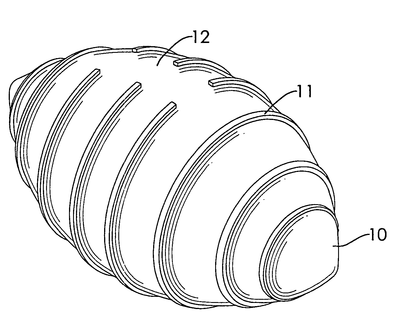
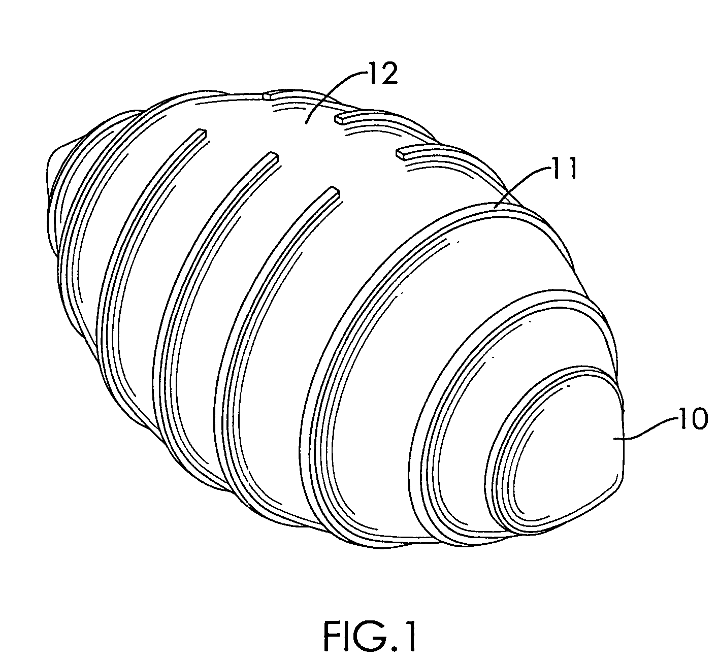
[0012] With reference to FIG. 1, it is noted that the bladder in accordance with the present invention includes an oval body (10) and a plurality of ribs (11) formed on an outer periphery of the body (10).

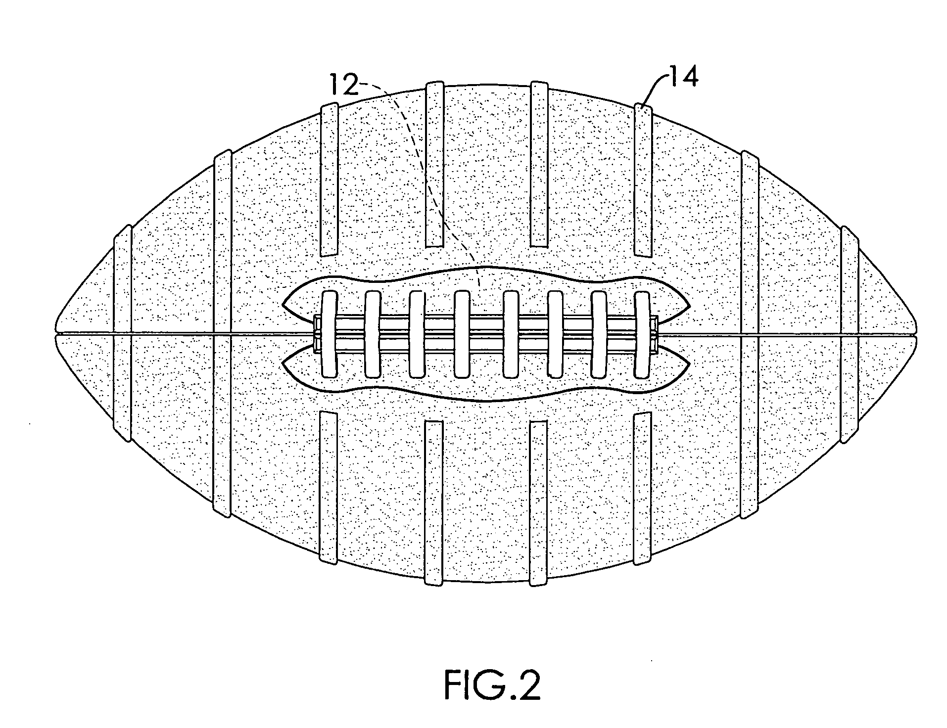
[0013] The ribs (11) on two opposite ends of the body (10) are annular in shape so that each of the ribs (11) on two ends of the body (10) surrounds the outer periphery of the body (10). A void (12) is defined in a central mediate portion of the body (10), which terminates the continuity of the ribs (11).

[0014] With reference to FIG. 2, it is noted that each rib (11) is under the skin of the football so that multiple protruding strips (14) are formed on the football and a seam (not numbered) is formed on the area where the void (12) is defined.

[0015] With reference to FIG. 3, from the cross sectional view of a portion of the football, it is seen that after the skin (13) is attached to the outer periphery of the bladder body, protruding strips (14) are formed and extended upward ...


PUM


Abstract

A football bladder includes an oval body and multiple ribs formed on an outer periphery of the oval body. After a skin is attached to the outer periphery of the oval body, protruding strips are formed on an outer periphery of the skin.

Description

BACKGROUND OF THE INVENTION [0001] 1. Field of the Invention [0002] The present invention relates to a bladder structure, and more particularly to a bladder structure of a football. [0003] 2. Description of the Prior Art [0004] In order to have a firm grip to a football, beside the provision of the seam on an outer periphery of the football, protruding ribs are also formed on the outer periphery of the football. However, due to frequent friction with the ground surface, a height of the protruding ribs is gradually reduced, which results in that the football is ended up in the landfill. [0005] To overcome the shortcomings, the present invention tends to provide an improved bladder structure to mitigate the aforementioned problems. SUMMARY OF THE INVENTION [0006] The primary objective of the present invention is to provide an improved bladder having thereon protruding ribs on an outer periphery of the bladder such that after the skins are firmly attached to the bladder, protruding str...

Claims


Application Information

Patent Timeline
IPC IPC(8): A63B41/00A63B39/00
CPCA63B41/02A63B2243/007A63B43/002
Inventor CHANG, YEN-LI
Owner CHANG YEN LI
Learn More