Electrolytic facility having pulses for killing germs and for removing fouling

a technology of electrolysis and pulses, which is applied in the direction of electrolysis components, separation processes, disinfection, etc., can solve the problems of increasing the manufacturing cost of typical electrolysis facilities and time-consuming soaping

Inactive Publication Date: 2007-07-26
SHYU WEN SHING
View PDF3 Cites 46 Cited by
  • Summary
  • Abstract
  • Description
  • Claims
  • Application Information

AI Technical Summary

Benefits of technology

[0013] The switch device includes at least one field effect transistor coupled to a central processing unit and coupled to the electrolyzing circuit and the pulse generating circuit for selectively switching on the electrolyzing circuit or the pulse generating circuit.

Problems solved by technology

However, the ultra violet light tubes or the micro filter devices may increase the manufacturing cost for the typical electrolytic facilities.
In addition, in typical electrolytic facilities, one or more cathode coppers or plates will be disposed in the electrode chamber and dipped within the electrolytic solution, and calcium materials, such as calcium carbonate CaCo3, and / or carbon materials will be deposited on the cathode coppers or plates to form a calcium fouling problem.
However, it is inconvenient and it is time consuming for soaping and washing the cathode coppers or plates with the lemon acid or the acetic acid.

Method used


Image

  • Electrolytic facility having pulses for killing germs and for removing fouling
  • Electrolytic facility having pulses for killing germs and for removing fouling
  • Electrolytic facility having pulses for killing germs and for removing fouling

Examples


Embodiment Construction

[0024] Referring to the drawings, and initially to FIG. 1, an electrolytic facility in accordance with the present invention is to provide pulses for killing germs and / or for removing fouling in an electrode chamber 10, and comprises an electric circuit 20 for conducting electrolyzing operation, and another electric circuit 30 for conducting high voltage pulse generating operation.

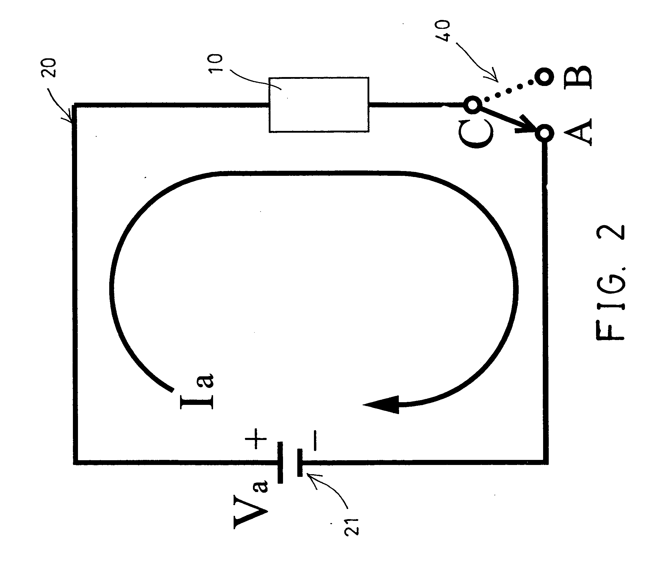
[0025] For example, as shown in FIGS. 1 and 2, the electrolyzing circuit 20 includes an electric power source 21 coupled to the electrode chamber 10 for generating or applying a typical or normal voltage Va and a typical or normal current Ia to the electrode chamber 10 and for conducting the typical electrolysis or electrolyzing operation.

[0026] As shown in FIGS. 1 and 3, the high voltage pulse generating circuit 30 includes an electric power source 31 coupled to the electrode chamber 10 for applying a high voltage Vb and a current Ib to the electrode chamber 10 and for generating one or more high voltag...


PUM

PropertyMeasurementUnit
volumeaaaaaaaaaa
timeaaaaaaaaaa
electrolyzing voltageaaaaaaaaaa

Abstract

An electrolytic facility includes an electrolyzing circuit coupled to an electrode chamber for conducting an electrolyzing operation, a pulse generating circuit coupled to the electrode chamber for generating pulses to kill germs and to remove fouling in the electrode chamber, and a switch device for selectively switching on the electrolyzing circuit or the pulse generating circuit. The pulses generated by the pulse generating circuit are preferably periodically generated in equal time interval, and preferably include a voltage contrary to the electrolyzing voltage for conducting the electrolyzing operation.

Description

BACKGROUND OF THE INVENTION [0001] 1. Field of the Invention [0002] The present invention relates to an electrolytic facility, and more particularly to an electrolytic facility having pulses generated for killing germs and / or for removing fouling in an electrode chamber. [0003] 2. Description of the Prior Art [0004] Typical electrolytic facilities may comprise an electrode chamber for receiving an electrolytic solution therein for electrolyzing purposes, and germs may be generated within the electrolytic solution or in the electrode chamber. [0005] Conventionally, one or more ultra violet light tubes or micro filter devices have been provided or used for killing germs or for filtering the germs. However, the ultra violet light tubes or the micro filter devices may increase the manufacturing cost for the typical electrolytic facilities. [0006] In addition, in typical electrolytic facilities, one or more cathode coppers or plates will be disposed in the electrode chamber and dipped wi...

Claims


Application Information

Patent Timeline
Patent Type & Authority Applications(United States)
IPC IPC(8): C02F1/461
CPCC02F1/46104C02F2201/46175C02F2201/4613C02F2001/46119
Inventor SHYU, WEN SHING
Owner SHYU WEN SHING
Why Eureka
Try Eureka