Positioning clamp for CD-ROM drives and diskette drives

a technology for cd-rom drives and clamps, applied in the direction of instruments, electrical equipment casings/cabinets/drawers, instruments, etc., can solve the problem of easy loss of screws, and achieve the effect of convenient and rapid positioning

Inactive Publication Date: 2007-07-12
IN WIN DEVELOPMENT INC
View PDF5 Cites 2 Cited by
  • Summary
  • Abstract
  • Description
  • Claims
  • Application Information

AI Technical Summary

Benefits of technology

[0005] The primary object of the present invention is to provide a clamp located at the two sides of a frame of a computer case such that a CD-ROM drive or a diskette drive is easily and rapidly positioned without the need of tools.

Problems solved by technology

As tools are needed to fasten the screws, it is time-consuming during assembling and disassembling, and moreover, screws are easily lost.

Method used


Image

  • Positioning clamp for CD-ROM drives and diskette drives
  • Positioning clamp for CD-ROM drives and diskette drives
  • Positioning clamp for CD-ROM drives and diskette drives

Examples


Embodiment Construction

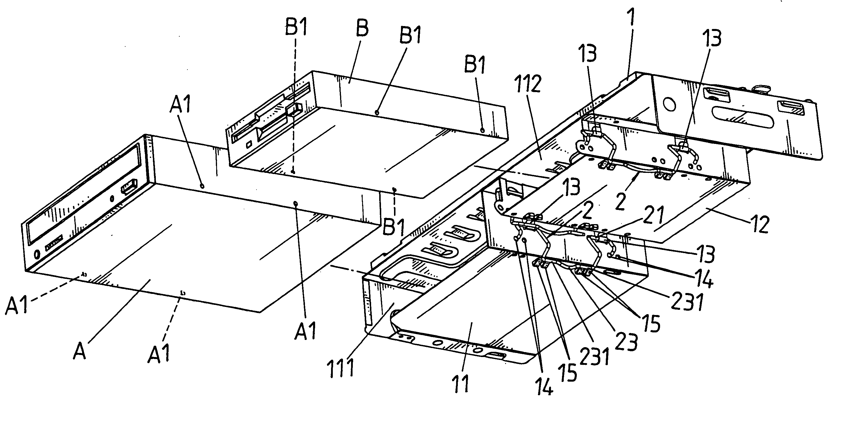
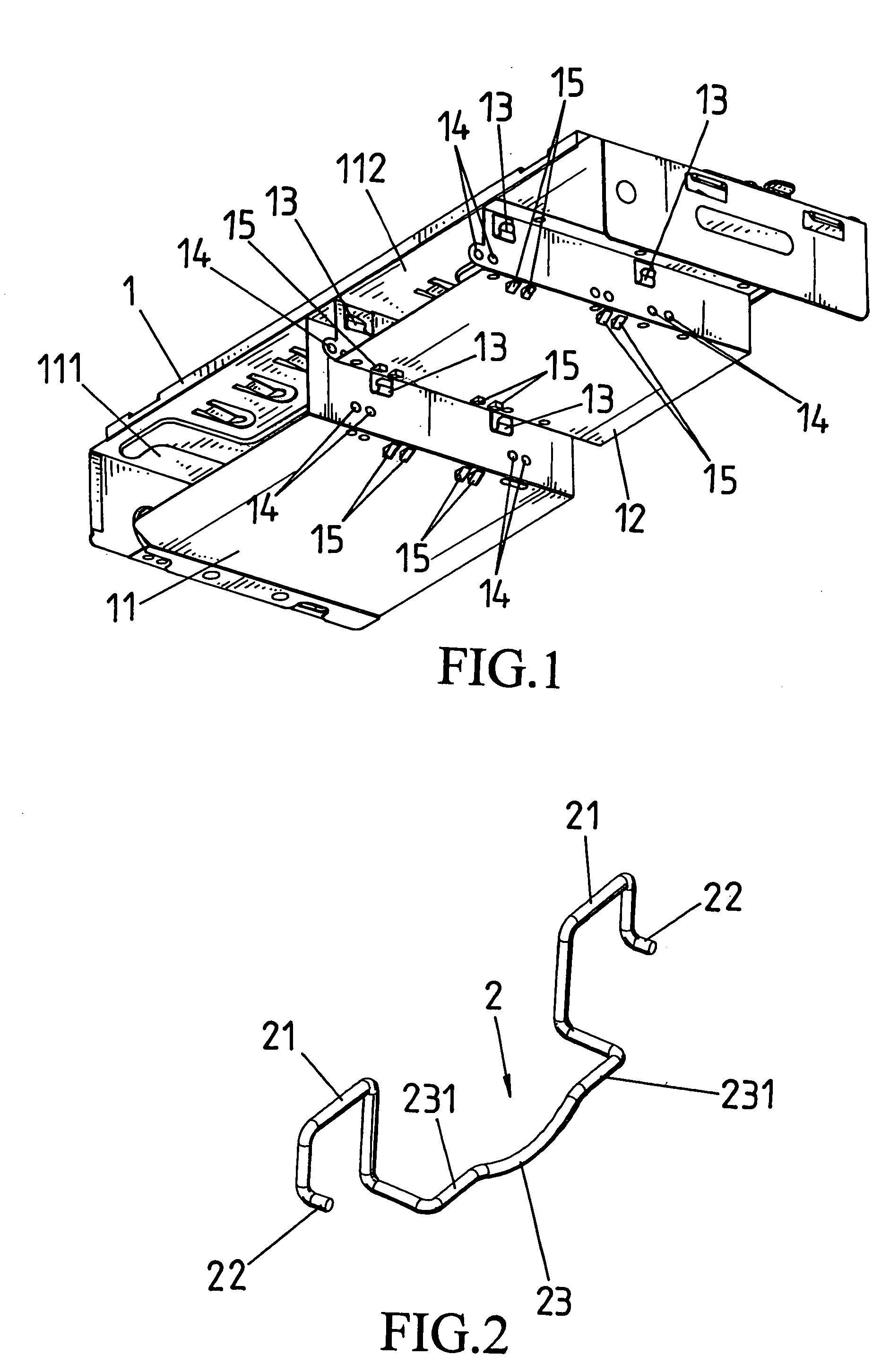
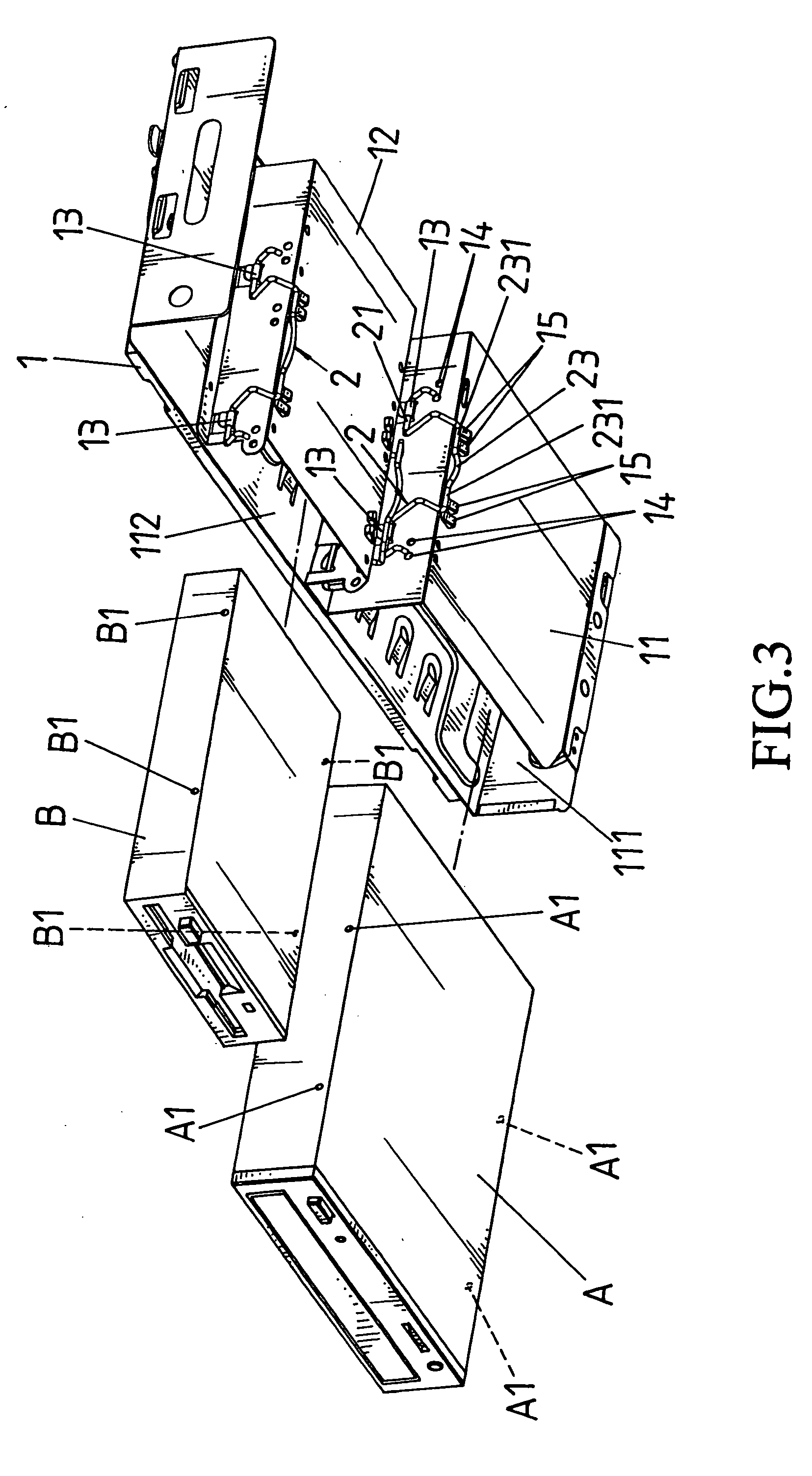
[0012] Referring to FIG. 1, a computer case 1 is of a horizontal-type (the computer case 1 can also be of a vertical-type,) wherein the computer case 1 forms a CD-ROM slot 111 and a diskette drive slot 112 with each of the two U-shaped frames 11 and 12 located at a corresponding bottom of the computer case 1 for inserting a corresponding CD-ROM drive A and a diskette drive B (FIG. 3.) Two slot holes A1 and B1 are disposed on the two sides of each of the CD-ROM drive A and the diskette drive B. Referring to FIG. 1, two clamp hooks 13 and at least one clamp-hole 14 are disposed on two side-plates on the two frames 11 and 12 of the computer case 1 respectively. At least one triangular clamp-piece 15 is disposed on a bottom-plate of the two frames 11 and 12 respectively. Referring to FIG. 2 and FIG. 3, a crooked clamp 2 can be clamped on the two frames 11 and 12. A horizontal member 21 at the two ends of the clamp 2 is pivotally connected inside each of the two clamp hooks 13. Then a ho...


PUM


Abstract

The present invention relates to a positioning clamp for CD-ROM drives and diskette drives, characterized in that no tools are required, but only clamps located at the periphery of a frame are needed to easily and rapidly position the CD-ROM drive and the diskette drive inside a CD-ROM slot and a diskette drive slot formed between a computer case and a computer frame

Description

BACKGROUND OF THE INVENTION [0001] (a) Field of the Invention [0002] The present invention relates to a clamp pivotally connected to the two sides of a frame of a computer case such that a CD-ROM drive or a diskette drive is securely positioned without the need of tools. [0003] (b) Description of the Prior Art [0004] Conventional CD-ROM drives and diskette drives are installed and positioned on a computer case by screws. As tools are needed to fasten the screws, it is time-consuming during assembling and disassembling, and moreover, screws are easily lost. SUMMARY OF THE INVENTION [0005] The primary object of the present invention is to provide a clamp located at the two sides of a frame of a computer case such that a CD-ROM drive or a diskette drive is easily and rapidly positioned without the need of tools. [0006] To enable a further understanding of the objectives and the technological methods of the invention herein, the brief description of the drawings below is followed by the...

Claims


Application Information

Patent Timeline
Patent Type & Authority Applications(United States)
IPC IPC(8): G06F1/16
CPCG06F1/187
Inventor LAI, VINCENT
Owner IN WIN DEVELOPMENT INC
Why Eureka
Try Eureka