
Dense reader system with improved listen before talk communications

a reader and listener technology, applied in the field of radio frequency identification (rfid) systems, can solve problems such as interfering interrogation signals and information loss, and achieve the effect of avoiding communication confli

Inactive Publication Date: 2007-06-21
SYMBOL TECH INC
View PDF11 Cites 33 Cited by
  • Summary
  • Abstract
  • Description
  • Claims
  • Application Information

AI Technical Summary

Benefits of technology

[0020] If the tag interrogation due to the another reader is occurring in the frequency channel, the first reader may switch frequency channels for further tag communications. Alternatively, the first reader may determine a time slot in which to attempt the second tag interrogation, in order to avoid conflict with communications by another reader.

Problems solved by technology

However, when multiple readers simultaneously send out interrogation signals to an overlapping group of tags, this may cause interference between the interrogation signals.
As a result, there may be signal conflict and / or signal degradation, resulting in loss of information.

Method used


Image

  • Dense reader system with improved listen before talk communications
  • Dense reader system with improved listen before talk communications
  • Dense reader system with improved listen before talk communications

Examples


example reader system embodiments

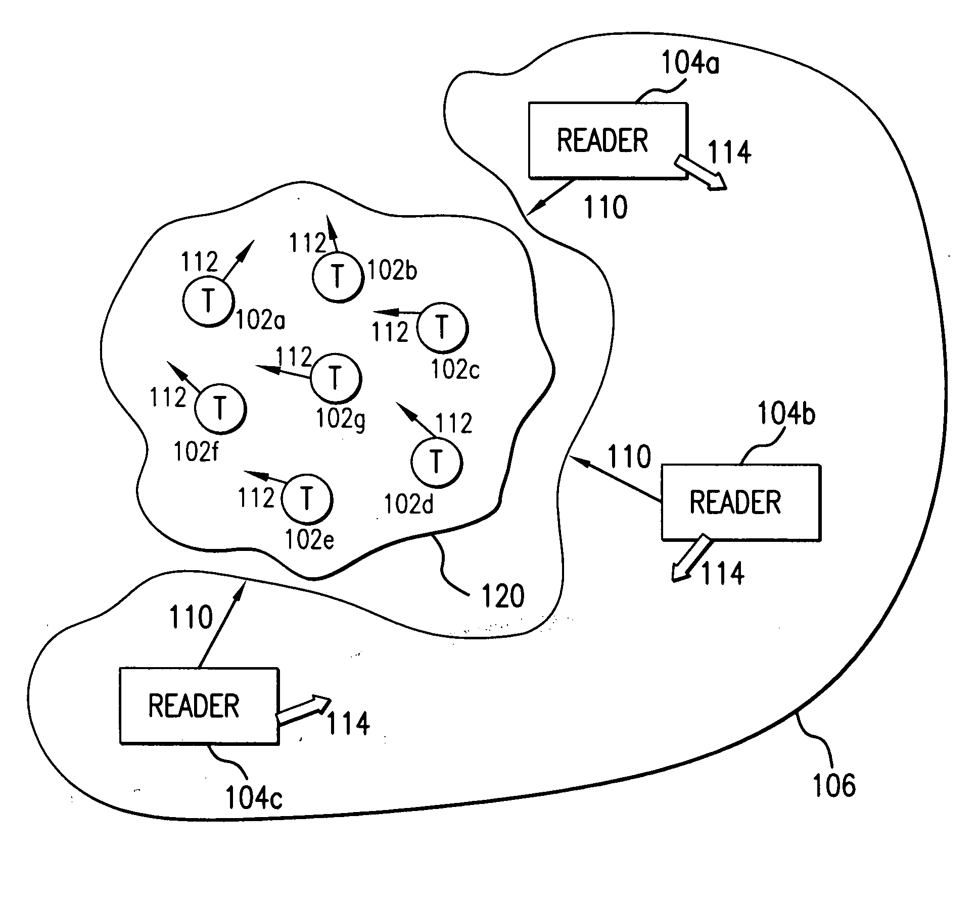
[0042] Before describing embodiments of the present invention in detail, it is helpful to describe an example RFID communications environment in which the invention may be implemented. FIG. 1 illustrates an environment 100 where RFID tag readers 104 communicate with an exemplary population 120 of RFID tags 102. As shown in FIG. 1, the population 120 of tags includes seven tags 102a-102g. According to embodiments of the present invention, a population 120 may include any number of tags 102.

[0043] Environment 100 includes a plurality of readers 104, such as readers 104a-104c. According to embodiments of the present invention, reader network 106 may include any number of readers 104, including tens, hundreds, thousands, or even more of readers 104. Reader network 106 can be referred to as a “dense reader” network, and environment 100 can be referred to as a “dense reader environment,” when a large number of readers are operating as members of the network.

[0044] In an embodiment, a re...

example network operational embodiments

[0060] In an embodiment, a reader network is self-configuring or self-assembling, where individual readers enter and exit the reader network while maintaining network performance. Such a reader network can be considered as a dynamic “plug and playsystem. Various reader exemplary operational configurations for reader networks are described below.

[0061] In embodiments, readers of a reader network operate in a “nearest neighbor” mode or environment which is dynamically self-configured. In an embodiment, operation of reader networks are “expert system” rule-based, where the expert-system rules govern the tag interrogation sequence ensuring little or no interference. As a reader enters a reader network, it wirelessly requests and downloads the rules for the environment. The downloaded rules are stored in the reader memory 302. Readers operate substantially autonomously based on the network rules.

[0062]FIGS. 4 and 5 depict example embodiments of reader networks of the present inventio...


PUM


Abstract

Methods, systems and apparatuses for RFID readers forming a reader network are described. In an aspect of the present invention, readers communicate according to a “Listen Before Talk” (LBT) protocol to avoid undesirable interference.

Description

CROSS-REFERENCE TO RELATED APPLICATIONS [0001] The following applications of common assignee are related to the present application, have the same filing date as the present application, and are herein incorporated by reference in their entireties: [0002]“Optimized Operation Of A Dense Reader System,” Atty. Dkt. No. 2319.0230000, U.S. Ser. No. ______; and [0003]“Smart RFID Reader Antenna,” Atty. Dkt. No. 2319.0250000, U.S. Ser. No. ______.BACKGROUND OF THE INVENTION [0004] 1. Field of the Invention [0005] The present invention relates generally to radio frequency identification (RFID) systems, and more particularly to systems and methods for communications among RFID readers. [0006] 2. Background Art [0007] Radio frequency identification (RFID) tags are electronic devices that may be affixed to items whose presence is to be detected and / or monitored. The presence of an RFID tag, and therefore the presence of the item to which the tag is affixed, may be checked and monitored by devic...

Claims


Application Information

Patent Timeline
Patent Type & Authority Applications(United States)
IPC IPC(8): H04Q5/22
CPCG06K7/0008
Inventor BANDY, WILLIAM R.POWELL, KEVIN J.
Owner SYMBOL TECH INC
Learn More