
Electrode container box, printing device and nozzle inspection method

Inactive Publication Date: 2007-06-14
SEIKO EPSON CORP
View PDF2 Cites 22 Cited by
  • Summary
  • Abstract
  • Description
  • Claims
  • Application Information

AI Technical Summary

Benefits of technology

[0006] The present invention was made in order to overcome such a problem, and has one object of providing an electrode container box that is to be used in the inspection of nozzles for clogging, and that is free from leakage of print recording liquid accumulated therein. In addition, another object is to provide a printing device that utilizes the electrode container box, and a nozzle inspection method according to which such an electrode container box can be utilized.
[0024] According to the nozzle inspection method, the electrode member electrically connected to the opposing electrode contained in the box member of the electrode container box penetrates the inside and outside of the box member in a liquid-tight manner. Thus, even when print recording liquid has accumulated in the box member after an inspection of nozzle clogging has already taken place, there is no leakage of the print recording liquid from any part of the box member that is being penetrated.

Problems solved by technology

In Patent Document 1, however, lead wire penetrating inside and outside of the cap connects the opposing electrode contained in the cap with an electric field detection unit located outside the cap, and there has been a risk that ink accumulated in the cap might leak as a result of the penetration.

Method used


Image

  • Electrode container box, printing device and nozzle inspection method
  • Electrode container box, printing device and nozzle inspection method
  • Electrode container box, printing device and nozzle inspection method

Examples


Embodiment Construction

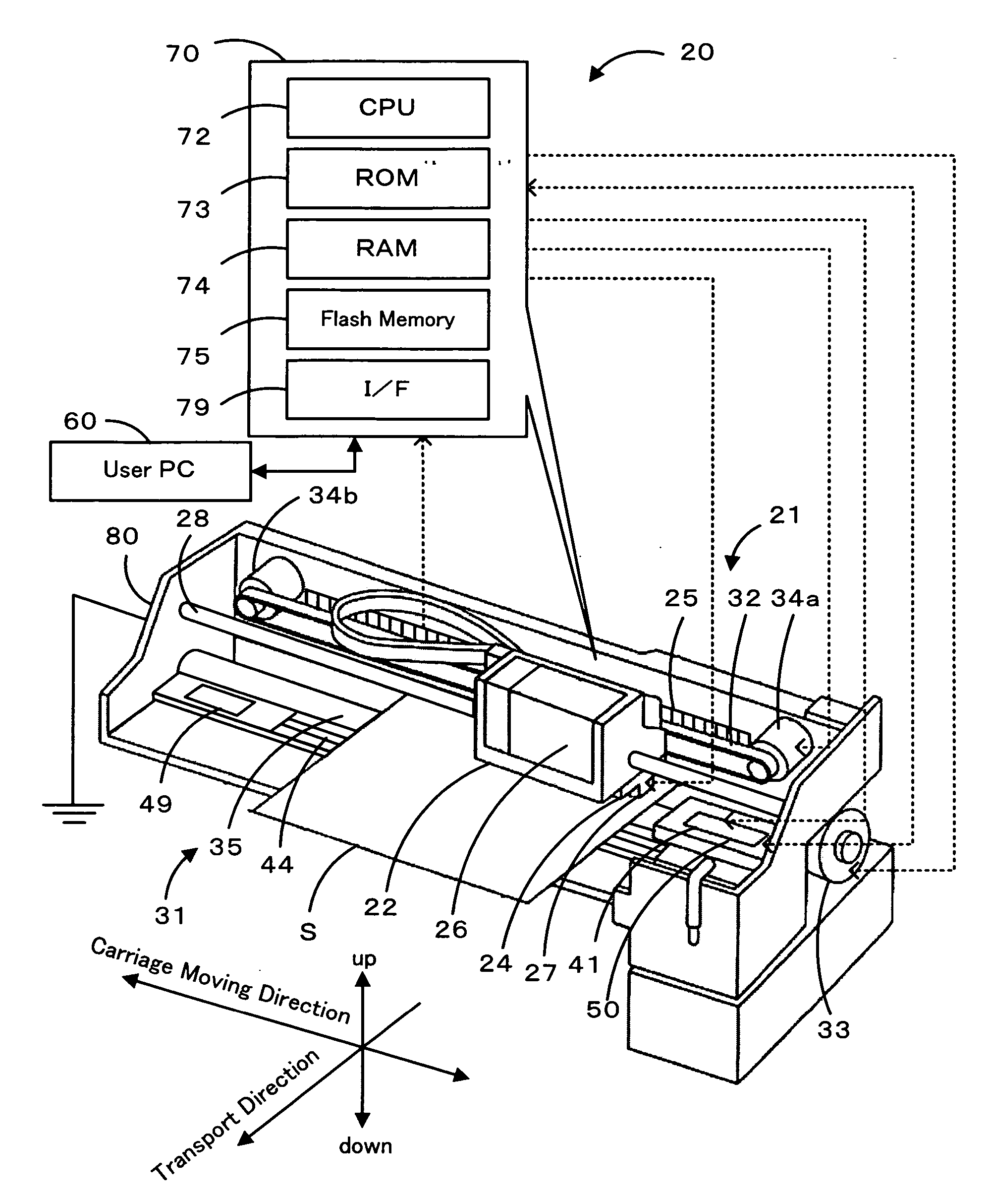
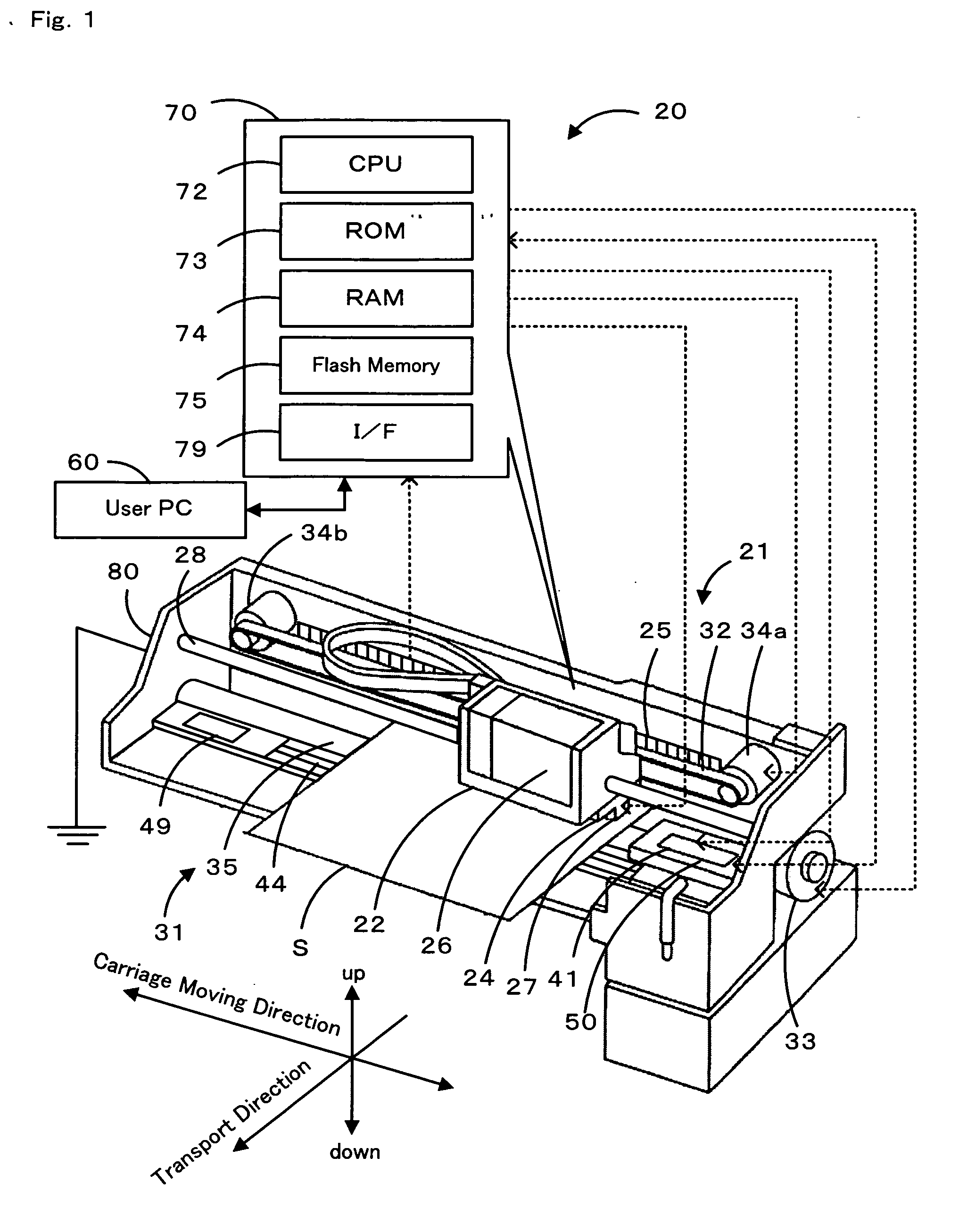
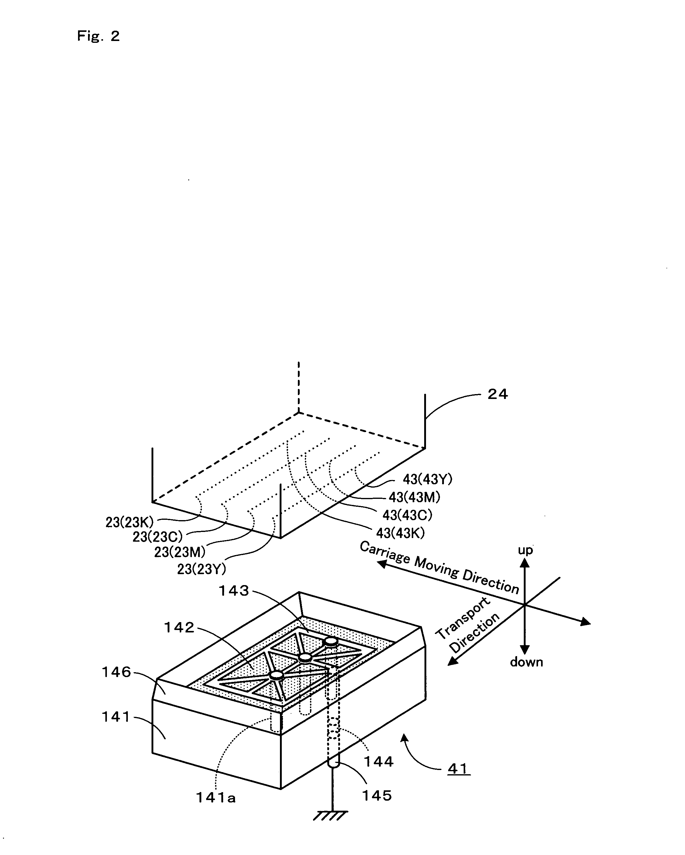
[0040] Next, one embodiment of the present invention is described. FIG. 1 is a block diagram schematically illustrating a configuration of an ink jet printer 20 that constitutes this embodiment. FIG. 2 is a perspective view in which a print head 24 is opposite to a cap 41. FIG. 3 is an illustration of a paper handling mechanism 31. FIG. 4 is an exploded perspective view of the cap 41. FIG. 5 is a block diagram schematically illustrating a configuration of a print head inspection device 50. FIG. 6 is an illustration of a cap elevator mechanism 90. FIG. 6 (a) illustrates a print head 24 that is not opposite to the cap 41. FIG. 6 (b) illustrates a print head 24 that is opposite to, and separated from, the cap 41. FIG. 6 (c) illustrates a print head 24 that abuts on the cap 41.

[0041] As illustrated in FIG. 1, the ink jet printer 20 of the present invention comprises: a printer mechanism 21 that performs printing by jetting ink droplets onto a recording sheet S to be transported over a ...


PUM


Abstract

A cap 41 is used for nozzle inspections for clogging on the basis of a waveform of an output signal at a print head 24 when, in a state in which a potential difference has been generated among the print head 24, a regulating member 143 that is the opposing electrode opposite to the print head 24, or an ink-absorbing member 142, an operation is performed of ejecting ink from the nozzles 23 of the print head 24 to an opposing electrode. The cap 41 comprises a box member 141 in which the regulating member 143 and the ink-absorbing member 142 are contained and an electrode pin 145 that penetrates the box member 141 in a liquid-tight manner, and that is electrically connected with the regulating member 143. Thus, even when ink accumulates in the box member 141 after a nozzle inspection for clogging has taken place, no ink will leak from the part that the electrode pin 145 penetrates.

Description

BACKGROUND OF THE INVENTION [0001] 1. Field of the Invention [0002] The present invention relates to an electrode container box, a printing device and a nozzle inspection method. [0003] 2. Description of the Prior Art [0004] As a conventional electrode container box used in the inspection of nozzles for clogging of a print head, known a type has been known of utilizing caps that cover nozzles of the print head at times that printing has been terminated, as for instance, disclosed in Patent Document 1. In Patent Document 1, an inspection of nozzle clogging takes place as follows. Specifically, an opposing electrode that is opposite to the print head is contained in the cap, and a potential difference is generated between the print head and the opposing electrode by not only grounding the opposing electrode to the ground but also by applying voltage to the print head. In such a condition, nozzles are inspected for clogging on the basis of changes that take place in an electric field a...

Claims


Application Information

Patent Timeline
IPC IPC(8): H01R13/625
CPCB41J2/16579
Inventor ENDO, HIRONORISHIMAZAKI, JUN
Owner SEIKO EPSON CORP
Learn More