
Gas blender with auxiliary mixed gas outlet

Active Publication Date: 2007-06-07
VYAIRE MEDICAL CONSUMABLES LLC
View PDF2 Cites 33 Cited by
  • Summary
  • Abstract
  • Description
  • Claims
  • Application Information

AI Technical Summary

Benefits of technology

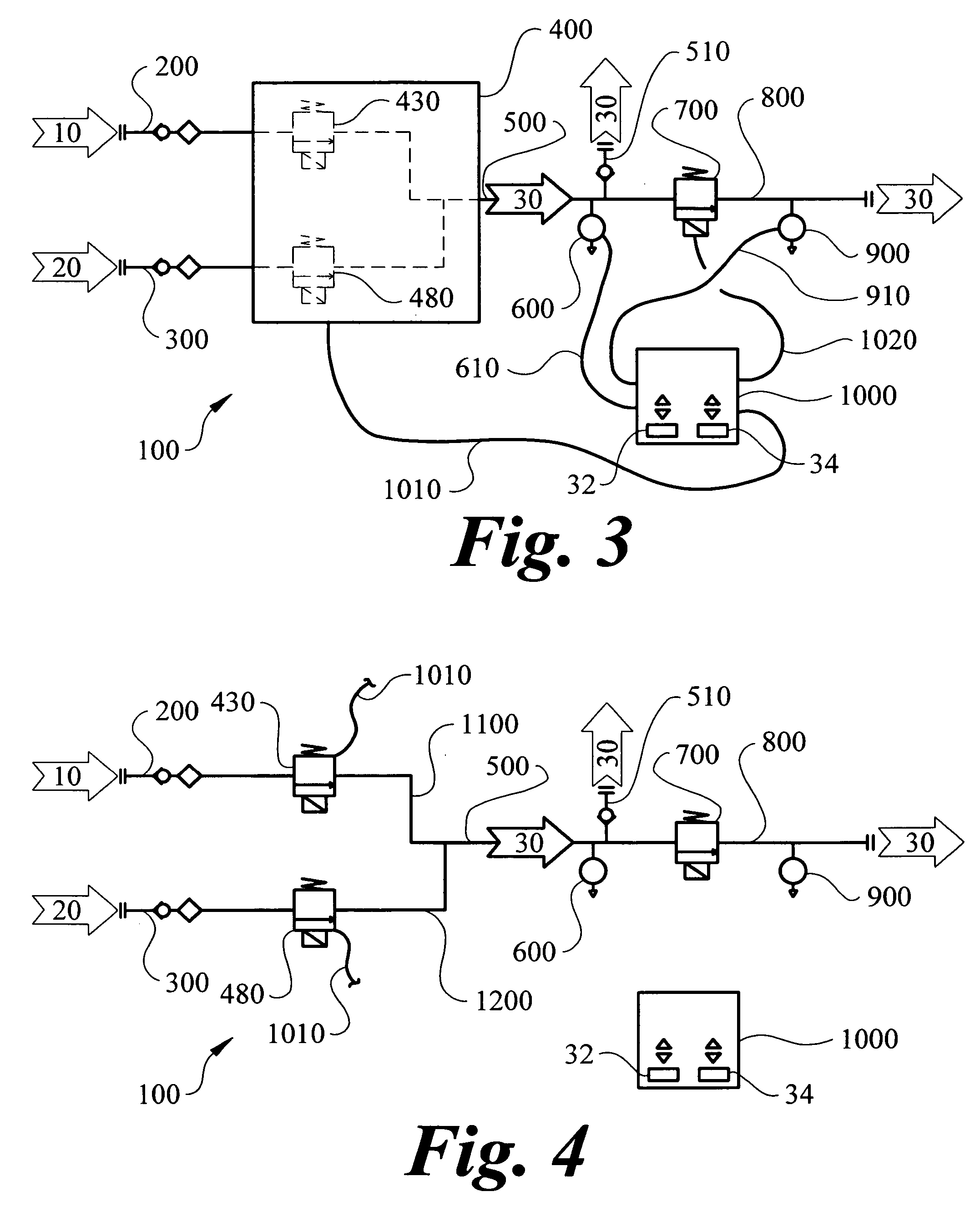
[0013] The predetermined mixture setpoint is a percentage of either the primary gas or the secondary gas that is desired in the mixed gas. The mixed gas then exits the gas mixing apparatus via the mixed gas distribution passageway. The mixed gas distribution passageway of the present invention has an auxiliary mixed gas outlet for supplying mixed gas at the predetermined mixture setpoint and a pressure of at least fifty percent of the primary gas source pressure, for use by the auxiliary piece of equipment. This ability to supply mixed gas at a pressure of at least fifty percent of the source pressure of the primary gas and the secondary gas, while also supplying mixed gas via another outlet at a reduced pressure or flow, is a significant advance.

Problems solved by technology

While many oxygen therapy devices have the ability to properly mix the medical compressed air and oxygen built into the device, several devices do not, and require connection to an external gas blender so that the device is supplied with pre-mixed gas.
Presently a limited number of commercially available devices incorporate an auxiliary mixed gas outlet, but these devices have a number of drawbacks.
First, it is believed that the presently available gas blenders having an auxiliary gas outlet can only supply mixed air via a treatment outlet or the auxiliary outlet, not both outlets at the same time.
Secondly, presently available auxiliary gas outlets often can only supply mixed gas at low flow rates, thereby limiting the types of auxiliary equipment that can be supplied with the mixed gas from the auxiliary gas outlet.

Method used


Image

  • Gas blender with auxiliary mixed gas outlet
  • Gas blender with auxiliary mixed gas outlet
  • Gas blender with auxiliary mixed gas outlet

Examples


Embodiment Construction

[0036] The gas blender with auxiliary mixed gas outlet (100) of the instant invention enables a significant advance in the state of the art. The preferred embodiments of the apparatus accomplish this by new and novel arrangements of elements that are configured in unique and novel ways and which demonstrate previously unavailable but preferred and desirable capabilities. The detailed description set forth below in connection with the drawings is intended merely as a description of the presently preferred embodiments of the invention, and is not intended to represent the only form in which the present invention may be constructed or utilized. The description sets forth the designs, functions, means, and methods of implementing the invention in connection with the illustrated embodiments. It is to be understood, however, that the same or equivalent functions and features may be accomplished by different embodiments that are also intended to be encompassed within the spirit and scope o...


PUM


Abstract

A gas blender with auxiliary mixed gas outlet for mixing a primary gas, generally air, and a secondary gas, generally oxygen, to obtain a mixed gas having several controlled characteristics. The gas blender may be incorporated into a Continuous Positive Airway Pressure (CPAP) device. The gas blender controls the mixing to produce the mixed gas having a predetermined mixture setpoint, generally an oxygen percentage, and a predetermined control setpoint, generally a pressure setpoint or flow rate setpoint. The gas blender provides an auxiliary mixed gas source for use by an auxiliary piece of equipment such as a nebulizer or resuscitation bag. The gas blender includes a primary gas inlet passageway, a secondary gas inlet passageway, a gas mixing apparatus, a mixed gas distribution passageway with an auxiliary mixed gas outlet, a gas sensor, a delivery sensor, a mixed gas delivery control valve, a mixed gas controlled passageway, and a controller.

Description

TECHNICAL FIELD [0001] The present invention generally relates to a gas mixing and control device, especially for a gas blending device particularly suited for supplying mixed gas to a Continuous Positive Airway Pressure (CPAP) medical device. BACKGROUND OF THE INVENTION [0002] Oxygen therapy is used to treat patients suffering from a wide variety of ailments and to assist in numerous treatments. One of the most important aspects of such therapy is obtaining the correct oxygen mixture and pressure of the treatment gas. A common form of oxygen therapy is accomplished through the use of a Continuous Positive Airway Pressure (CPAP) device. As those skilled in oxygen therapy will recognize, numerous other auxiliary therapy devices that require mixed gas are used in conjunction with CPAP therapy. Such auxiliary devices include nebulizers and resuscitation bags. [0003] Medical compressed air and oxygen are mixed, or blended, to obtain the correct oxygen mixture and pressure of the treatme...

Claims


Application Information

Patent Timeline
IPC IPC(8): A61M15/00A61M16/00
CPCA61M16/08A61M16/12A61M16/204A61M2205/70A61M2202/0208A61M2016/0027A61M2016/003A61M16/107A61M16/209
Inventor SMITH, MICHAEL S.VOSS, GREGBLISS, PETERHALPERIN, SCOTT
Owner VYAIRE MEDICAL CONSUMABLES LLC
Learn More