
Electro-mechanical transmission with six speed ratios and a method of redesigning a transmission

a technology of electronic transmission and transmission design, applied in the direction of battery/cell propulsion, transportation and packaging, etc., can solve the problems of increasing fuel consumption and emissions beyond the ideal case, and custom hybrid systems typically have limited application, so as to achieve optimal regenerative braking and hybrid functionality

Inactive Publication Date: 2007-05-24
GM GLOBAL TECH OPERATIONS LLC
View PDF3 Cites 15 Cited by
  • Summary
  • Abstract
  • Description
  • Claims
  • Application Information

AI Technical Summary

Benefits of technology

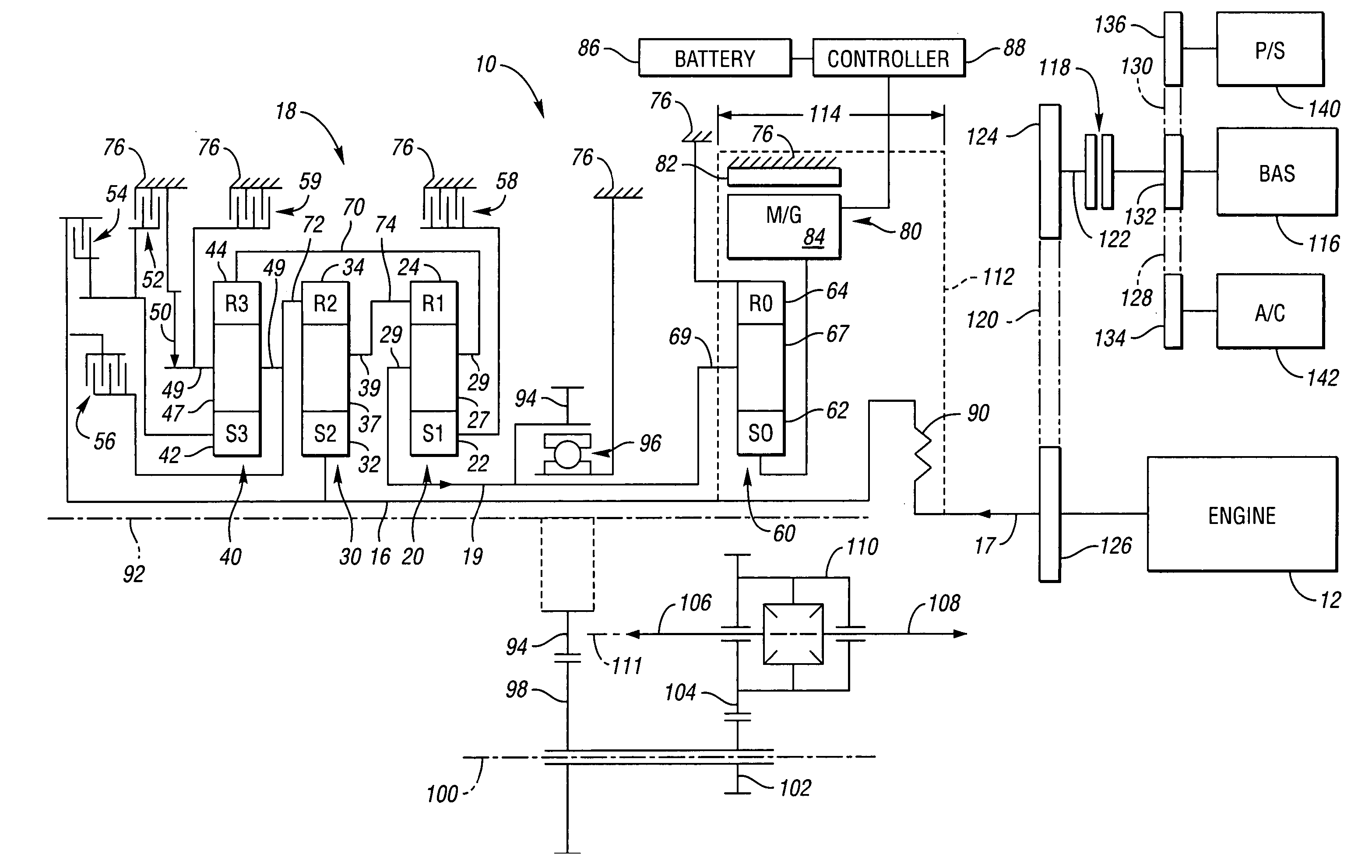
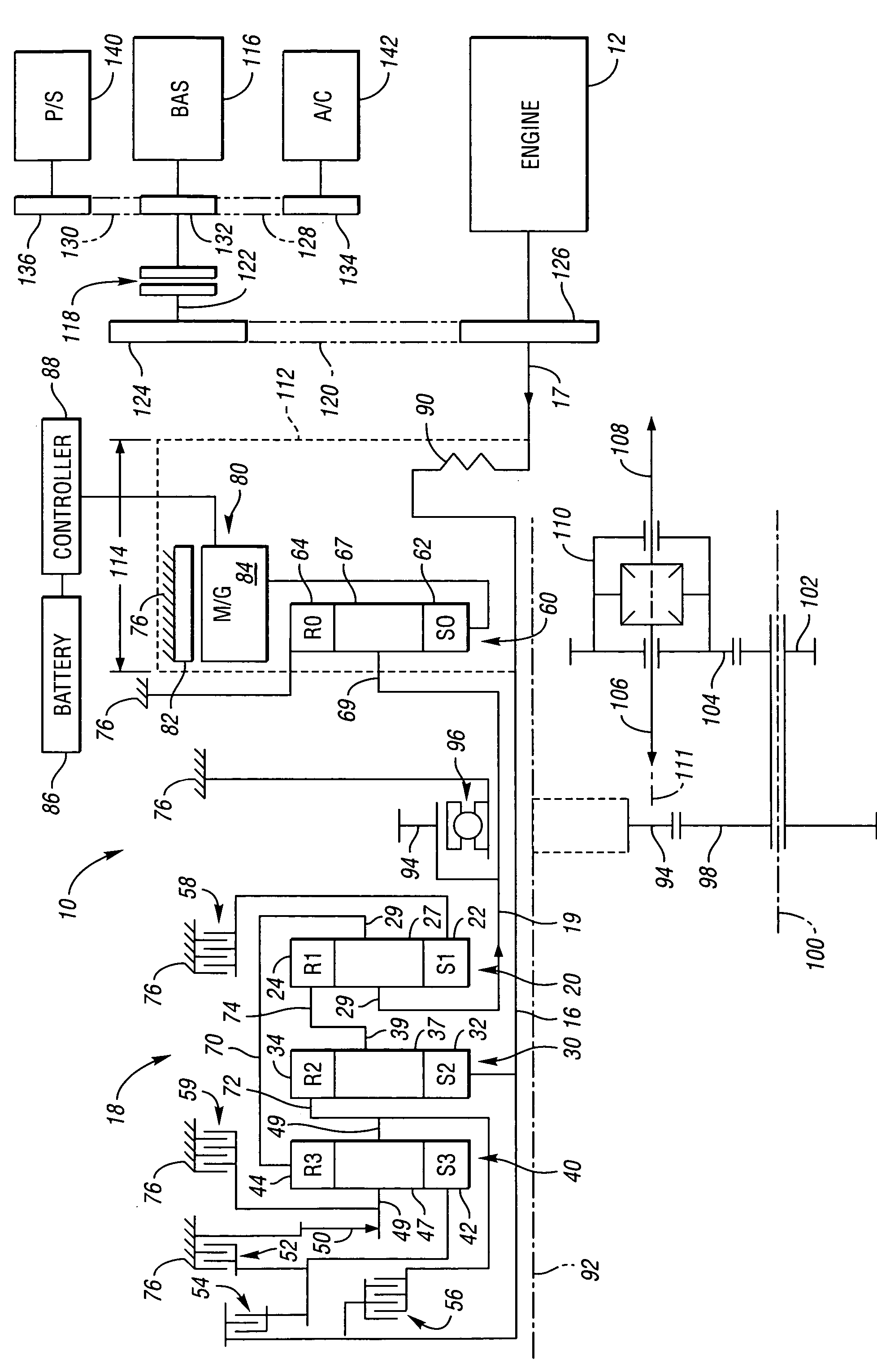
[0009] An electromechanical transmission is provided that may be implemented with minimal design changes in an existing powertrain. Thus, hybrid functionality and its inherent benefits may be achieved with minimal design changes and their associated costs. Specifically, hybrid system components are placed within a base transmission envelope by eliminating a torque converter. The axial space previously occupied by the torque converter is utilized to install an electric motor / generator, an additional planetary gear set for electric motor torque multiplication, and, optionally, a damper. Preferably, the output torque path remains unchanged. The motor / generator is connected to the output torque path and is unaffected by gear shifting pattern, thus allowing optimal regenerative braking to occur.

Problems solved by technology

The wide variation in the demands that vehicles typically place on internal combustion engines increases fuel consumption and emissions beyond the ideal case for such engines.
Such custom hybrid systems typically have limited application to existing powertrains because significant vehicle modification would be required due to packaging limitations.

Method used


Image

  • Electro-mechanical transmission with six speed ratios and a method of redesigning a transmission
  • Electro-mechanical transmission with six speed ratios and a method of redesigning a transmission

Examples


Embodiment Construction

[0018] The drawing depicts an electromechanical transmission 10. An engine 12 is operatively connected to the transmission 10 for providing power thereto. Specifically, the engine 12 powers an input member 17. Power flows from the input member 17 through a plurality of gear members 18 to an output member 19. The plurality of gear members 18 includes a first planetary gear set 20, a second planetary gear set 30 and a third planetary gear set 40. The first planetary gear set 20 includes a sun gear member 22 circumscribed by a ring gear member 24 (labeled S1, R1, respectively) and a carrier member 29 on which a plurality of rotatable pinion gears 27 are supported. The pinion gears 27 intermesh with both the sun gear member 22 and the ring gear member 24.

[0019] The planetary gear set 30 also includes a sun gear member 32, a ring gear member 34 and a carrier member 39 (labeled S2, R2, respectively) on which a plurality of pinion gears 37 are rotatably supported. The pinion gears 37 inte...


PUM


Abstract

An electromechanical transmission is provided having an input member for receiving power from an engine and output member. A plurality of gear members is operable for changing speed ratio between the input member and the output member. The input is connected with one of the gear members and the output member is connected with another of the gear members. A motor / generator is continuously operatively connected with the output member (via a planetary gear set) in parallel with the gear member that is continuously connected with the output member. The motor / generator is packaged axially between the input member and the plurality of gear members. The motor / generator is packaged in a packaging space typically utilized for a torque converter in a nonelectro-mechanical transmission. Thus, redesign of the nonelectro-mechanical transmission to achieve the electromechanical transmission involves a minimal number of steps.

Description

TECHNICAL FIELD [0001] The invention relates to electromechanical transmissions and transmission design. BACKGROUND OF THE INVENTION [0002] Internal combustion engines, particularly those of the reciprocating piston type, currently propel most vehicles. Such engines are relatively efficient, compact, lightweight, and inexpensive mechanisms by which to convert highly concentrated energy in the form of fuel into useful mechanical power. A novel transmission system, which can be used with internal combustion engines and which can reduce fuel consumption and emissions, may be of great benefit to the public. [0003] The wide variation in the demands that vehicles typically place on internal combustion engines increases fuel consumption and emissions beyond the ideal case for such engines. Typically, a vehicle is propelled by such an engine, which is started from a cold state by a small electric motor and relatively small electric storage batteries, then quickly placed under the loads from...

Claims


Application Information

Patent Timeline
Patent Type & Authority Applications(United States)
IPC IPC(8): F16H3/72
CPCB60L11/123B60K2006/4808B60L2270/145B60W10/02B60W10/08B60W10/115B60W20/00F16H3/66F16H3/725F16H2037/088F16H2200/0052F16H2200/2012F16H2200/2043F16H2200/2097Y02T10/6217Y02T10/6221Y02T10/626Y02T10/7077B60K6/365B60K6/387B60K6/40B60K6/48B60K6/547B60L11/14B60L50/61B60L50/16Y02T10/62Y02T10/7072Y02T10/70B60W2710/021
Inventor SOWUL, HENRYKHENDRICKSON, JAMES D.
Owner GM GLOBAL TECH OPERATIONS LLC
Learn More