
Remote control means

Inactive Publication Date: 2007-05-03
BURY
View PDF4 Cites 32 Cited by
  • Summary
  • Abstract
  • Description
  • Claims
  • Application Information

AI Technical Summary

Benefits of technology

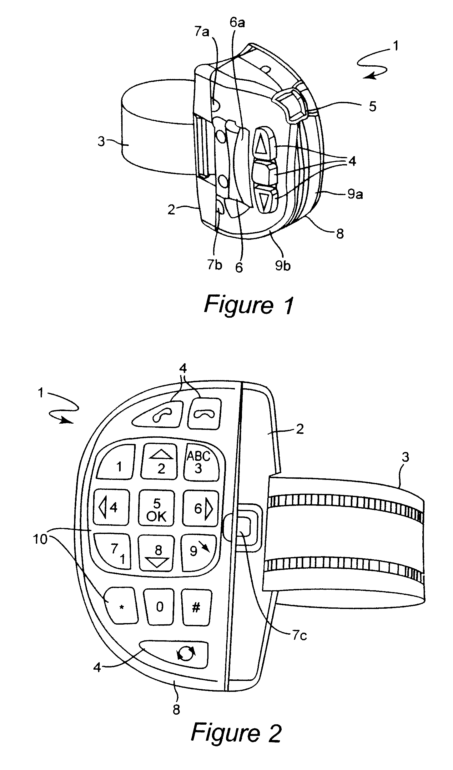
[0007] First of all, this new position of operator control keys on the rear face of the housing of the remote control means has the disadvantage that this operator control key cannot be seen by the driver. However, the operator control keys on the rear face of the housing of the remote control means can be operated in an ergonomically favorable fashion and space in the housing of the remote control means which has not previously been used can be utilized for optional additional operator control keys on the rear face of the housing of the remote control means. These advantages fully compensate for the disadvantage of not being able to see the operator control keys since a proficient driver will quickly become familiar with the new operator control keys on the rear face of the remote control means.
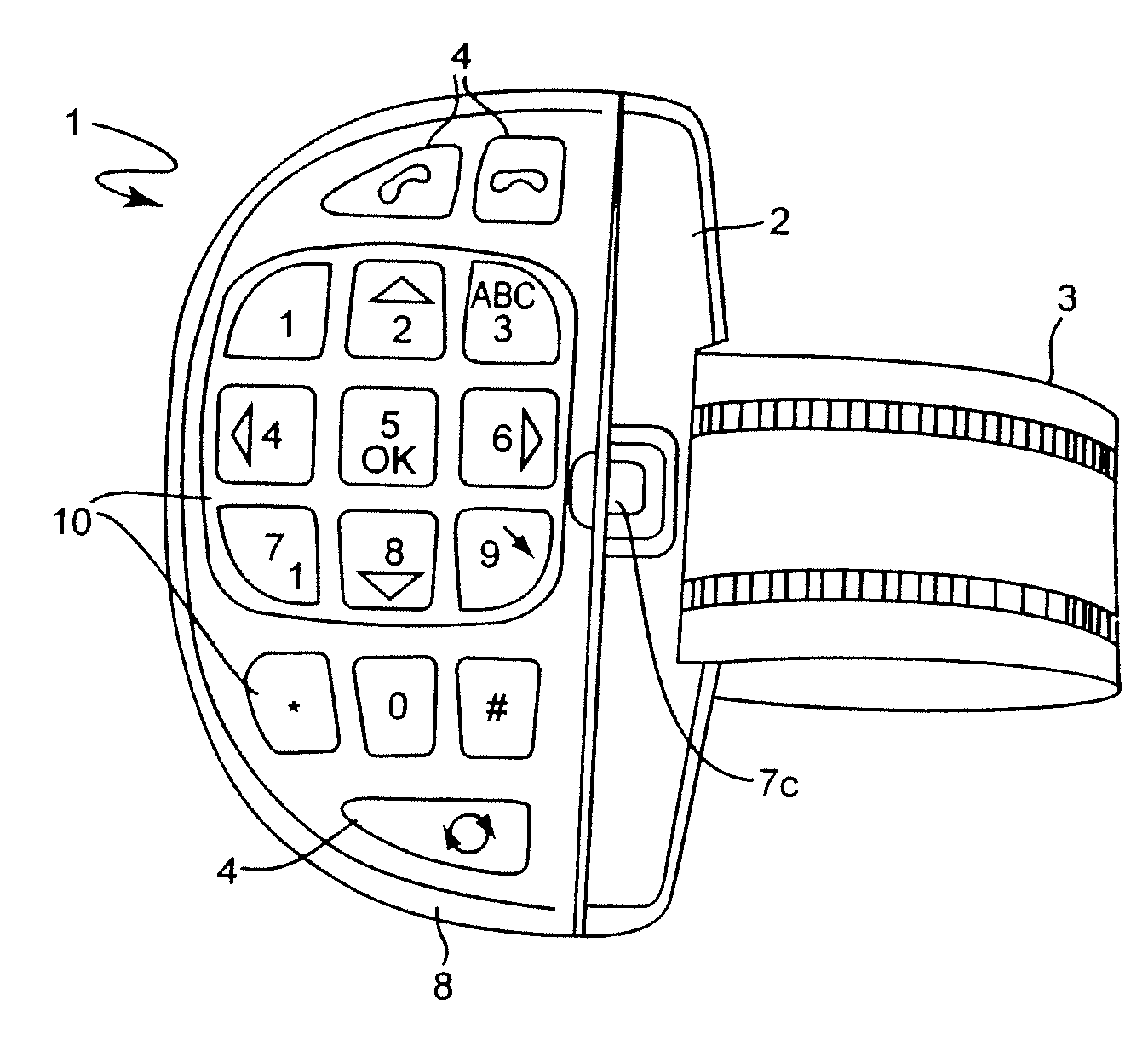
[0010] It is also advantageous when the operator keys on the front face comprise a 10-digit numerical keypad plus special characters. This numerical keypad which is extended in comparison to the previously customary operator control key arrangements has the advantage of simple operator control, for example of telephones.

Problems solved by technology

However, the options provided by conventional remote control means are limited by the space available in the housing of the remote control means and the frontal position.
First of all, this new position of operator control keys on the rear face of the housing of the remote control means has the disadvantage that this operator control key cannot be seen by the driver.
These advantages fully compensate for the disadvantage of not being able to see the operator control keys since a proficient driver will quickly become familiar with the new operator control keys on the rear face of the remote control means.

Method used


Image

  • Remote control means
  • Remote control means
  • Remote control means

Examples


Embodiment Construction

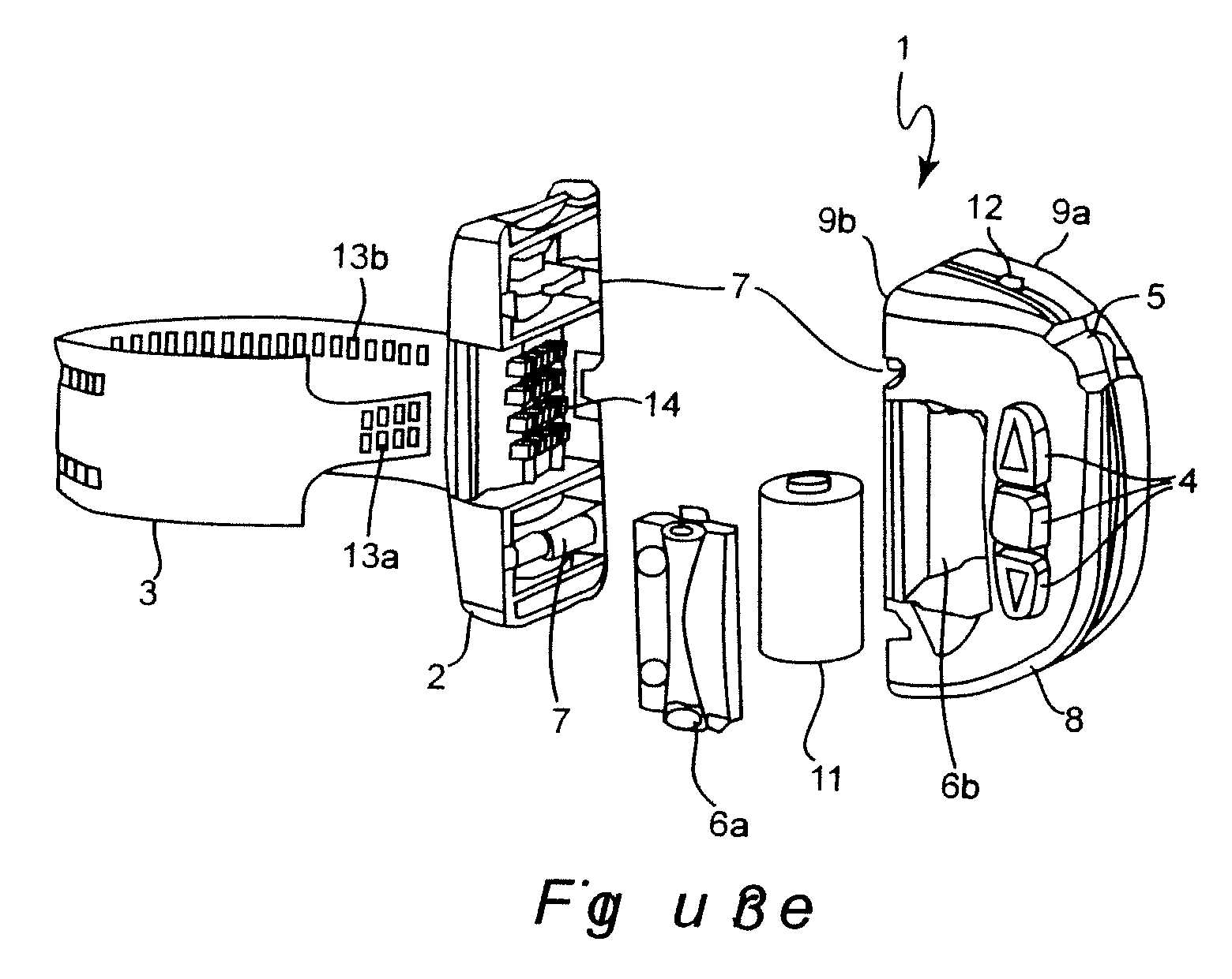
[0019]FIG. 1 shows a view of the rear of a remote control means 1 from the side, it being possible to attach said remote control means to a holder 2 on the steering wheel of a vehicle. To this end, a belt 3 is provided which is passed around the steering wheel rim and attached to the side of the holding means 2. The connection between the remote control means 1 and the steering wheel is reinforced by an additional adhesive pad on the bearing area of the holding means 2 in relation to the steering wheel rim in order to prevent the remote control means 1 from slipping or twisting.

[0020] It can be seen that operator control keys 4 are arranged on the rear face of the remote control means 1 in such a way that the driver can comfortably reach said operator control keys with his fingertips when gripping the steering wheel. The operator control keys 4 can be used, for example by operating the upwardly and downwardly directed arrow keys, to scroll up or down through an operator control men...


PUM


Abstract

A remote control for electronic devices in motor vehicles, having a holding part with attachment elements for mounting the holding part on a steering wheel in a releasable manner, having operator control keys on a housing of the remote control means, and having a unit for transmitting control signals, which are triggered by operating the operator control keys, to the at least one electronic device, has at least one operator control key which is arranged on the rear face of the housing of the remote control, which rear face points away from the driver when the remote control is mounted on the steering wheel, in such a way that a driver can use his fingertips to operate the operator control key when gripping the steering wheel.

Description

BACKGROUND OF THE INVENTION [0001] 1. Field of the Invention [0002] The invention relates to a remote control means for electronic devices in motor vehicles, having a holding means with attachment elements for mounting the holding means on a steering wheel in a releasable manner, having operator control keys on a housing of the remote control means, and having a unit for transmitting control signals, which are triggered by operating the operator control keys, to the at least one electronic device. [0003] Remote control means of this type which are to be retrofitted to a steering wheel are known particularly for operating hands-free systems, navigation systems, car radios, etc. Arranging the remote control means on the steering wheel means it is possible to operate these electronic devices without the driver having to take his hands off the steering wheel. This leads to increased traffic safety. DESCRIPTION OF THE RELATED ART [0004] In conventional remote control means which are to b...

Claims


Application Information

Patent Timeline
IPC IPC(8): G06F17/00
CPCB60R11/0264B60R2011/001B60R2011/0059B60R11/02B60R11/0258G06F3/0202G06F3/0219G06F3/0231
Inventor PIEKARZ, ROMAN
Owner BURY
Learn More