
Transfer seat with rotatable wing

Inactive Publication Date: 2007-04-26
TUBULAR FABTORS IND
View PDF19 Cites 5 Cited by
  • Summary
  • Abstract
  • Description
  • Claims
  • Application Information

AI Technical Summary

Benefits of technology

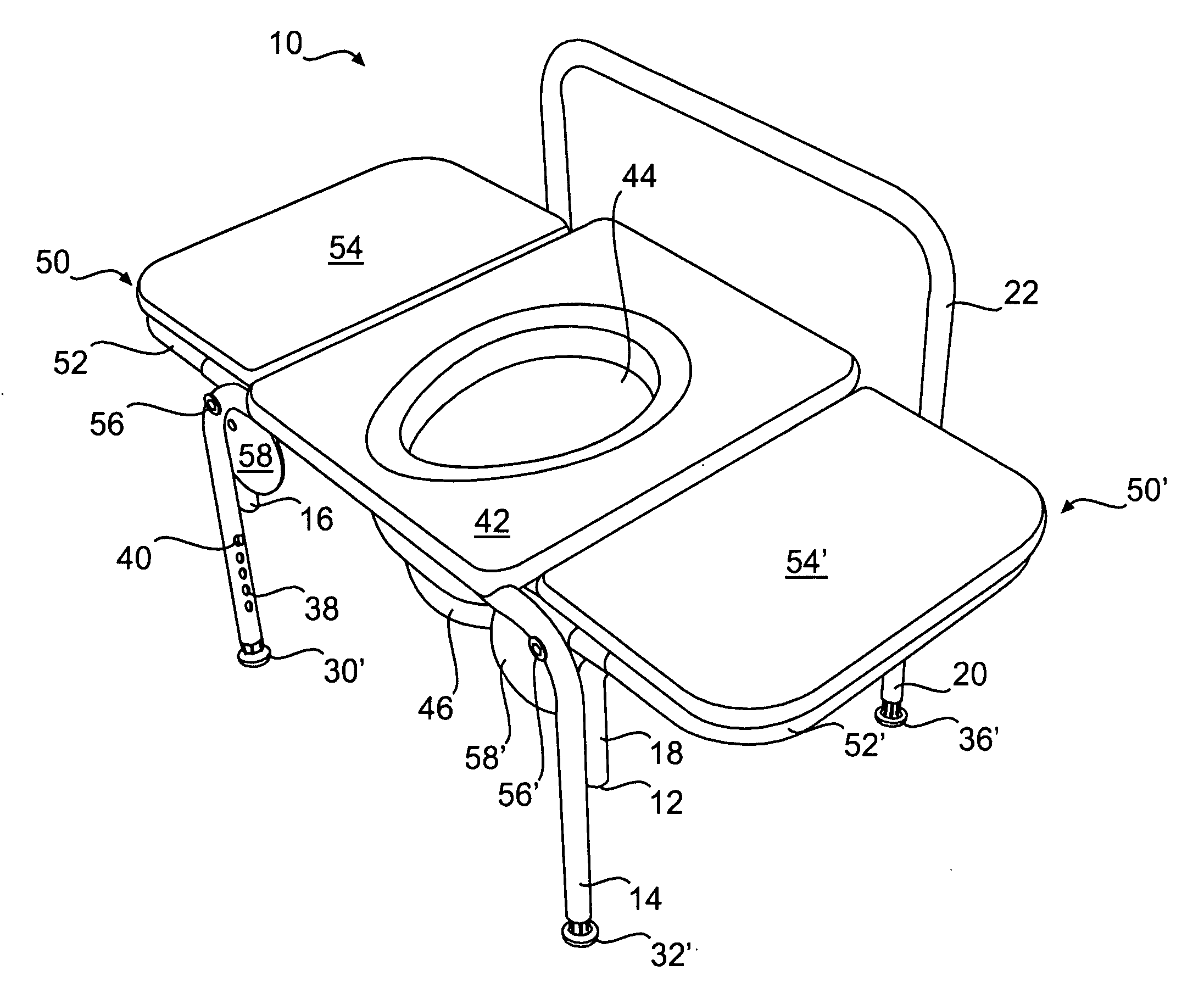
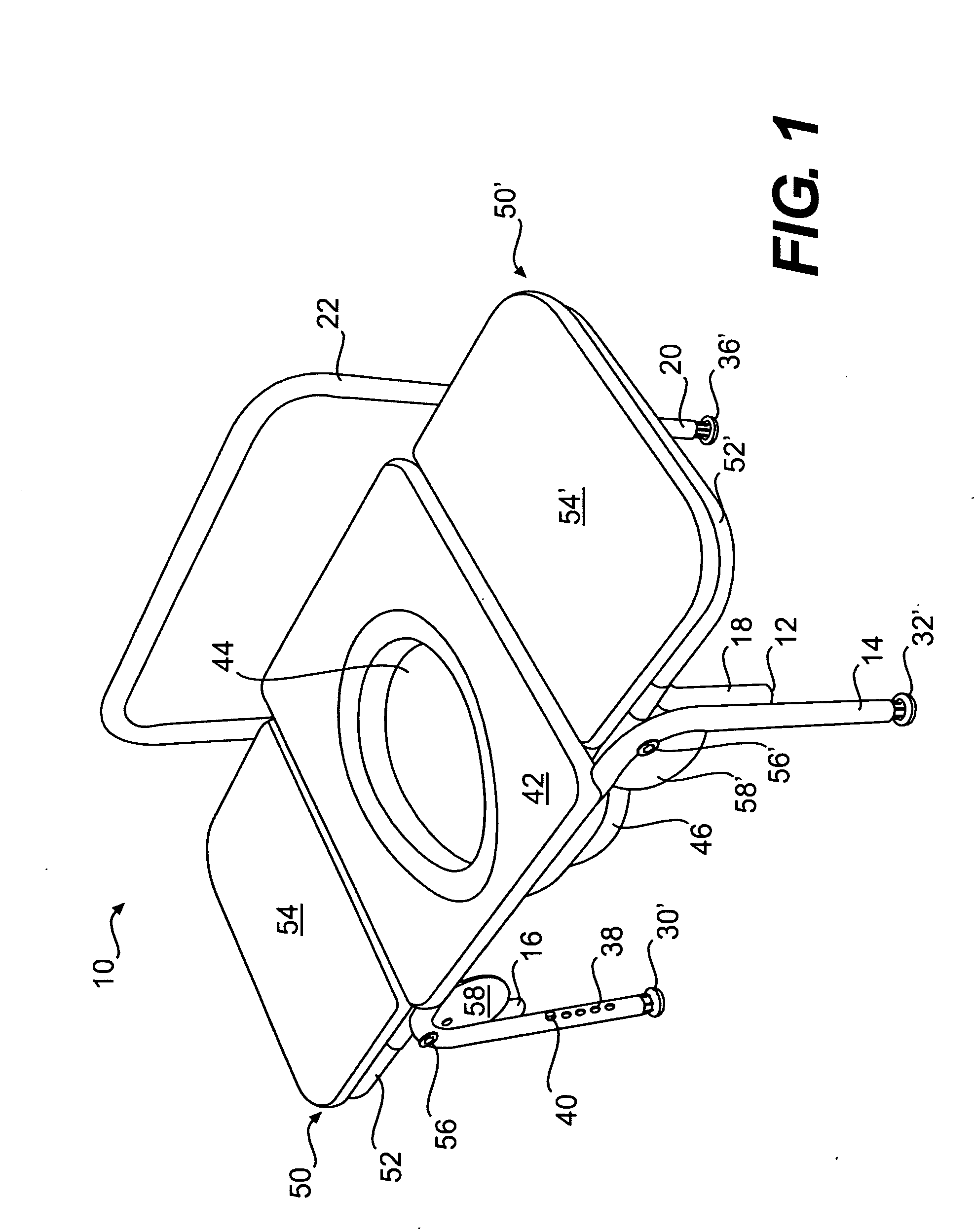
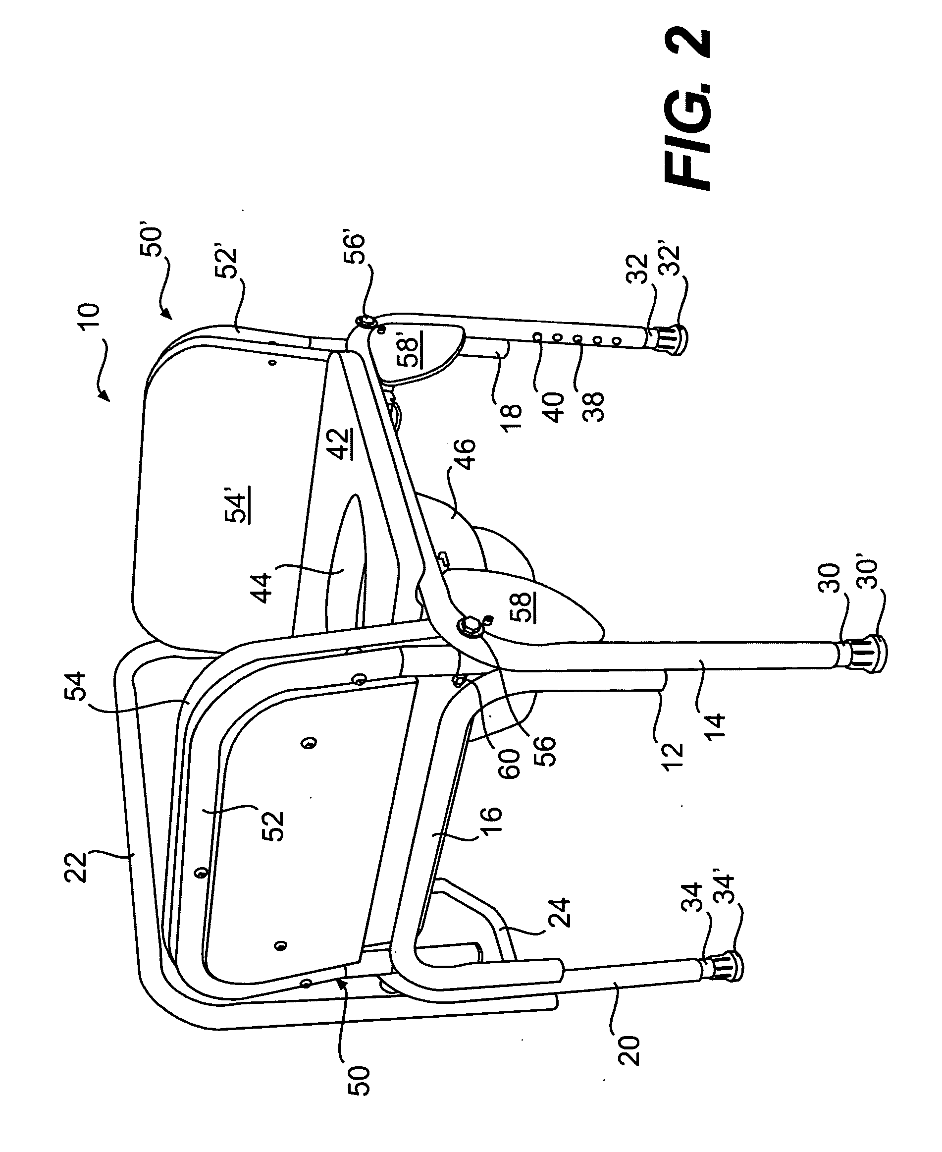
[0011] The transfer seat of the present invention facilitates obese, infirm, elderly or otherwise handicapped individuals access to a commode receptacle. The transfer seat is typically positioned next to a bed, piece of furniture, wheelchair, or other patient support. The wing can be positioned in a substantially horizontal position (or ‘transfer position’) so that it is usable to facilitate a patient's transfer onto the seating platform. In one embodiment, the frame provides some load support when the wing is in the transfer position. In another preferred embodiment, the frame prevents the wing from rotating substantially below a horizontal angle relative to the seating platform. It is envisioned that a less than horizontal angle may be also be provided.
[0012] The wing can also be positioned in a substantially vertical (or ‘upright position’) where it simulates a traditional arm rail found on portable commodes. The upright position serves to retain and / or support a patient on the seating platform. Placing the wing in the upright position facilitates transporting the transfer seat. The ability to put the wing in the upright position also allows the transfer seat to be positioned in locations that a fixed length transfer platform would not fit.

Problems solved by technology

Individuals that are injured, elderly, obese, or have other infirmities find it difficult to use existing bedside or portable commodes.
Known commodes are problematic for many patients, including obese patients, for a number of reasons, including the placement of arm rails, gaps between the bed and commode, and the like.
However, patients using a bedside commode are not necessarily bed ridden and, therefore, may attempt to transfer to the commode from another support surface (couch, wheelchair, etc.) from either side of the commode.
Wheelchair-bound patients, in particular, may access a commode from either side, but they may have difficulty transferring to commodes with fixed arm rails.
The problems with these continuous, planar supports are numerous.
For instance, the fixed length platform makes it difficult to position the commode adjacent to a patient based on room size, furniture arrangements, or the like.
Other problems are apparent to one skilled in the art.
Rear positioned platforms are impractical and / or of very little use to a typical patient based on one or more of the above shortcomings.
For instance, the transfer seat cannot be placed alongside the bed because the platform extends to the posterior of the toilet.
A toilet with a posteriorly placed platform does not facilitate a patient's access to the commode from the sides of the commode, which is the more typical approach.

Method used


Image

  • Transfer seat with rotatable wing
  • Transfer seat with rotatable wing
  • Transfer seat with rotatable wing

Examples


Embodiment Construction

[0026] Turning now to a more detailed description of the present invention, there is illustrated in FIGS. 1-3 a preferred embodiment of a transfer seat 10. As illustrated, a frame 12 includes the following frame members: a front bar 14, a left bar 16, a right bar 18, a rear bar 20, a back support 22, a left brace 24, and a rear brace 26. Front bar 14 is connected by left bar 16 and right bar 18 to rear bar 20. The bars and back support are generally inverted, U-shaped pieces in that they each have two vertical portions connected by rounded corners to an upper, horizontal portion. Front bar 14 and rear bar 20 are spaced apart in a parallel relationship. Left bar 16 and right bar 18 are also spaced apart in a parallel relationship. The vertical portions of the left and right bars 16, 18 are secured to corresponding vertical portions on front and rear bars 14, 20 by welding, fasteners, adhesives, or the like.

[0027] The vertical portions of back support 22 overlap and are in contact wi...


PUM


Abstract

The invention relates to a device and method for facilitating a portable commode user's transfer onto the commode by providing a transfer seat that includes at least one rotatable wing adjacent at least one side of a portable commode seating platform. The transfer seat includes a frame, a seating platform supported by the frame with an opening, and a human waste receptacle under the opening. The rotatable wing(s) is secured to the transfer seat adjacent to the seating platform.

Description

FIELD OF THE INVENTION [0001] The present invention relates, in general, to a transfer seat. The transfer seat of the present invention includes at least one rotatable wing. BACKGROUND OF THE INVENTION [0002] Bedside or portable commodes typically include tubular frames where the frames support a user above a portable or fixed installation receptacle. More specifically, such commodes include seating platform to support a user or patient above the portable or fixed installation receptacle to support a user or patient. The seating platforms are generally rotatable, removable, or fixed to the frame, but the platform must include an opening to allow a patient to pass waste into the receptacle. These commodes optionally include a back rail to support a patient or for aesthetic reasons and / or a lid that can be selectively placed over the platform opening. It is also known to include arm rails to support or confine the user on the commode. These arm rails may be fixed, adjustable, or remov...

Claims


Application Information

Patent Timeline
IPC IPC(8): A61G7/02A47K11/06
CPCA61G7/02A61G7/103A61G9/00A61G2200/34A61G5/1002
Inventor BATTISTON, JOSEPH
Owner TUBULAR FABTORS IND
Learn More